This section describes the different steps followed to produce various wood engraved items on a CNC Milling Machine using one 2D vector file on your own at the Fab Lab.
Step 1 : Designing the part

In order to digitally produce any object you need to have its virtual design. This is to be done using any Computer Aided Design (CAD) software.
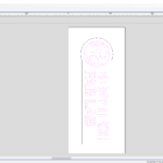
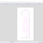
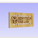
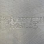
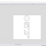
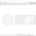
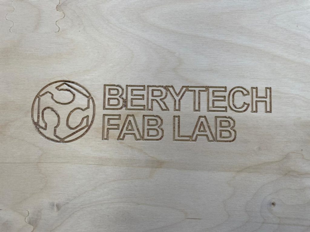
In this example the Berytech Fab Lab logo was designed on Adobe Illustrator.
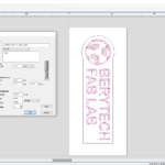
Step 2: Exporting Sketch to .DXF format
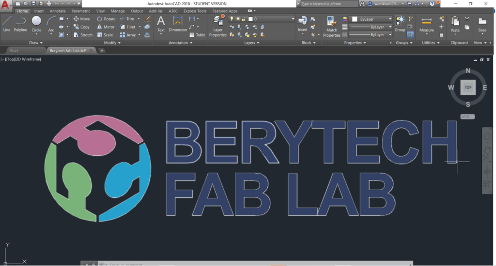
To extract the Vector File from the Logo design, open the file in Adobe Illustrator, and then export it to .DXF format. This file will then be imported to the V-Carve Software were the different milling jobs will be prepared.
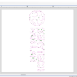
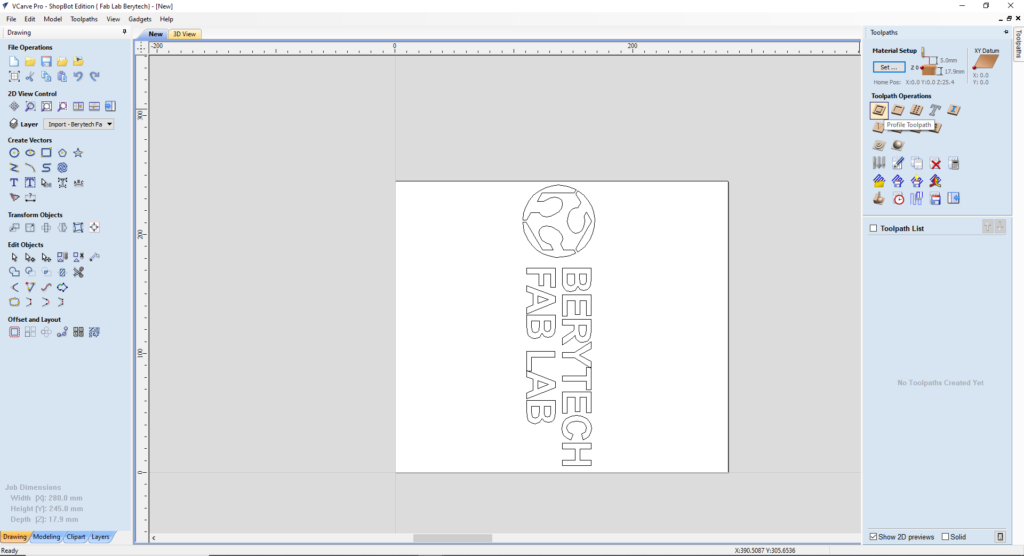
Step 3: Preparing G-Code on V-Carve
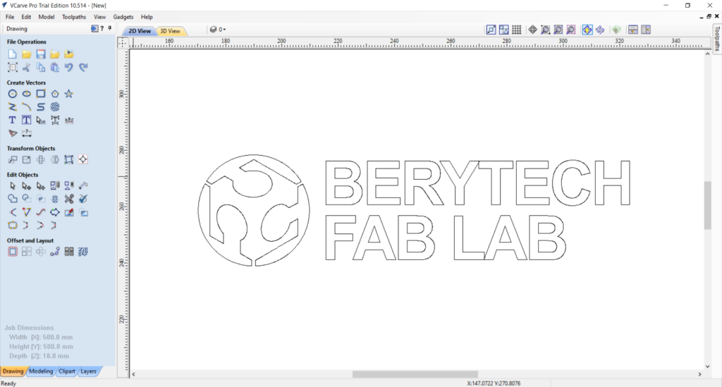
To perform any milling job, from any vector file, you need to prepare the g-code first, that will guide the CNC machine on the toolpath it should be milling. This step should be done using V-Carve, or any other preparation software of your choice. There are many various toolpath options that you can use for milling a 2D vector file, among which are:
- Profile Toolpath: is used to cut around or along a vector. Options provide the flexibility for cutting shapes out with optional Tabs / bridges plus an Allowance over/undercut to ensure perfect edge quality.
- Pocket Toolpath: is used to remove large areas of material. It removes the areas contained inside the selected vectors.
- V-Carve/Engraving Toolpath: is used to remove large areas of material using a V-Bit. It removes the areas contained inside the selected vectors.
- Texturing Toolpath: uses a specialized toolpath algorithm and the shape of the tool to generate a textured finish on the part.
To prepare the G-code, the following steps are usually followed on the V-Carve software for any Toolpath Option you choose:
- Open new page.
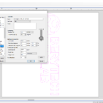
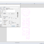
- Job Setup: Input Material Dimensions (x, y, & z). Take into consideration the lost area because of the screws used to fix the board.
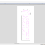
- Import the DXF file by selecting: “File” > “Import” > “Import Vectors” > Choose the 2D Model
- Move your design to your preferred position with respect to the material you are milling.
- Select the Toolpath Operation that you would like to perform.
- Generate the Path for job. To do so, choose the Tool used and the various settings (Cut Depth, Passes, Texture, Ramp…) that you prefer that would guide the Job Toolpath.
- When everything is set, press “Calculate”, to calculate your toolpath.
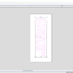
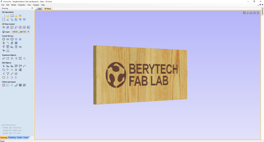
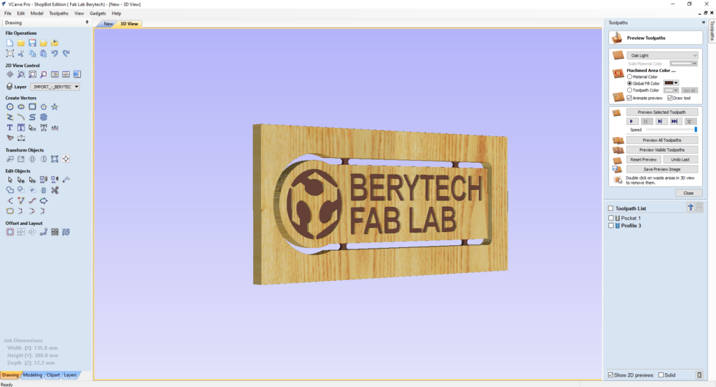
- Select the “Preview Toolpath” button, to visualize the milling job, and make sure the results are as expected. The 3D preview mode also allows the job to be viewed in different material types with the option to paint the machined regions with a Fill Color. If you notice any problems in the preview, make sure to go back and review all your settings to make sure that everything is running fine.
- Check machining time. To do that, select the “Toolpaths Summary” button.
Save Toolpath files in your dedicated folder. To do that, select the “Save Toolpath” button. This option allows toolpaths to be saved in the appropriate file format needed to drive the CNC machine.
Step 4: Preparing the CNC Machine and Zeroing the Tool Position
The next step is to set the zero position of the machine on the material that will be used.
To do so, those steps are usually followed:
- Manually move the router to the desired X and Y position, and then zero the X and Y from the control panel.
- Zero the Z-Axis using the automatic zeroing option on the Shopbot software. The plate is positioned under the milling bit on the surface of the board, and the “Z-zero” button is selected. This process is fully automated.
Step 5: Performing the Milling Job
The G-code is first imported to the Shopbot software and the job is then launched. The various milling jobs are illustrated in the next section.
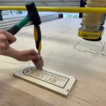
Step 6: Remove the Milled Parts
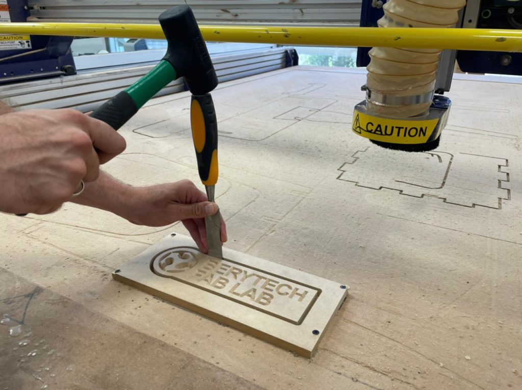
Once the parts are ready, cut all tabs using a Wood Chisel and remove the part from the main body.
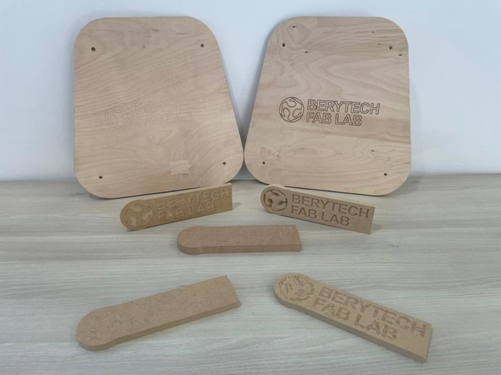
Different Toolpaths and Results
In this section, we will show in details the different toolpath options that can be used to mill any material of your choice, using the same vector file, and we will show images and videos to show the preparation steps, the milling process, and the final results for each example.
Option 1: Profile Toolpath
This option is used to cut around or along a vector. Cutting around a vector is mainly used to cut an object with a certain shape from a specific material, either from the outside, or from the inside, depending on its position. This option can also be used to mill with a certain depth at a certain line, using any bit of your choice. The examples below describe how Profile Toolpath milling along a vector is performed using both a 6mm Ball Nose Bit and a V Bit.
-
6mm Ball Nose Bit
Toolpath Preparation
To prepare the toolpath, follow the following steps:
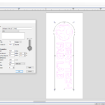
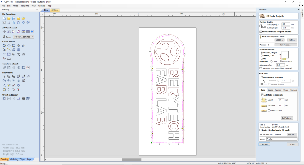
- Select the “2D Profile Toolpath” button.
- Select the logo outline as the vector followed for cutting.
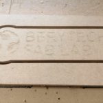
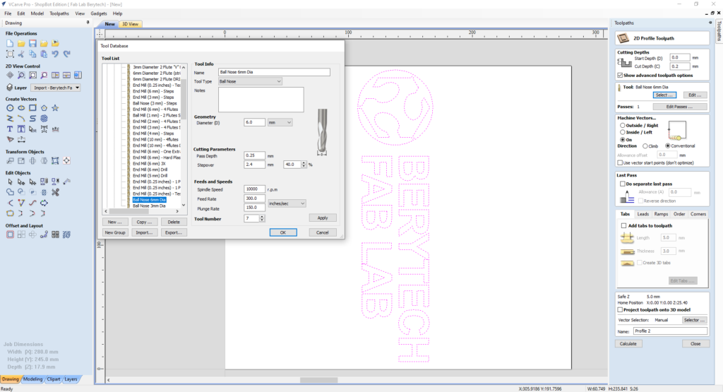
- Choose the Start Depth and Cut Depth. In this example we used 0.2 mm, as a cut depth, as we want to partially engrave the logo.
- Select the tool used for outline cutting. In this example, we used a 6mm Ball Nose Mill.
- Choose your preferred machining tool position with respect to the chosen outline vector. In this example we choose the “On” option, so that the tool cut the material along the chosen vector.
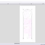
When everything is set, press “Calculate”, to calculate your toolpath.
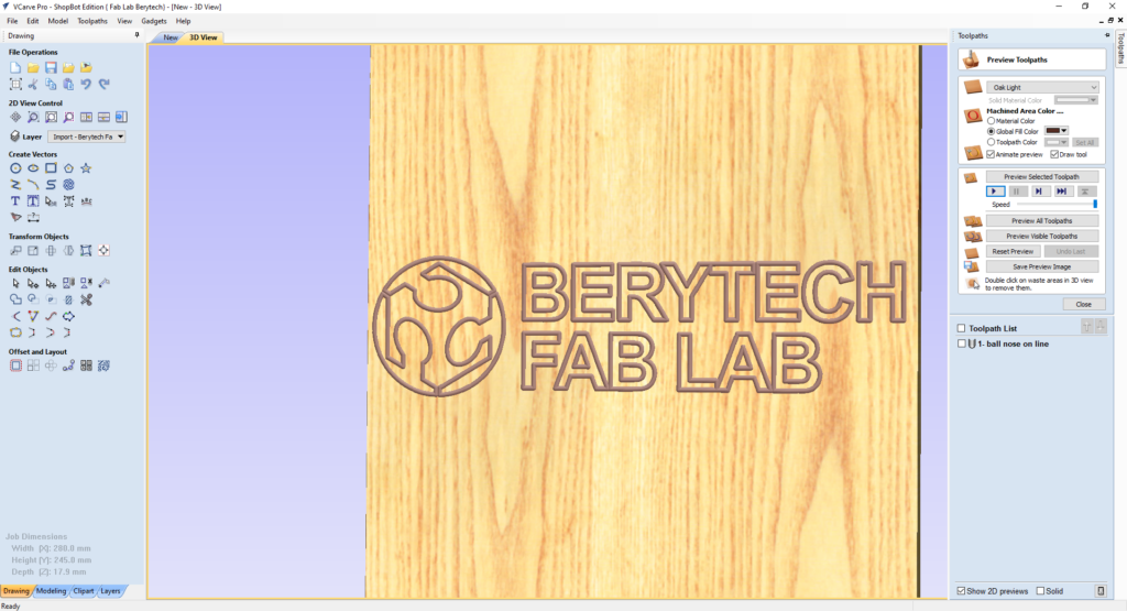
Select the “Preview Toolpath” button, to visualize the milling job, and make sure the results are as expected. If you notice any problems in the preview, make sure to go back and review all your settings to make sure that everything is running fine.
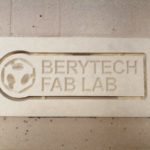
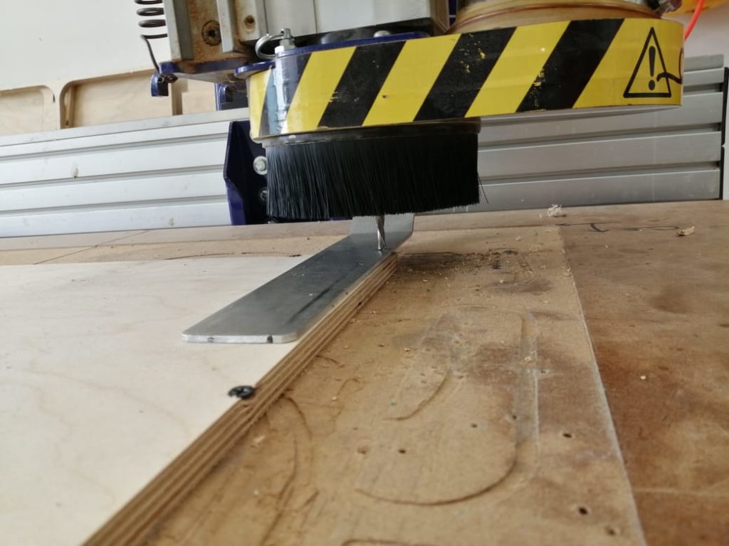
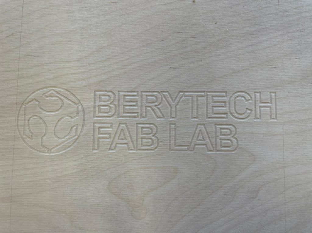
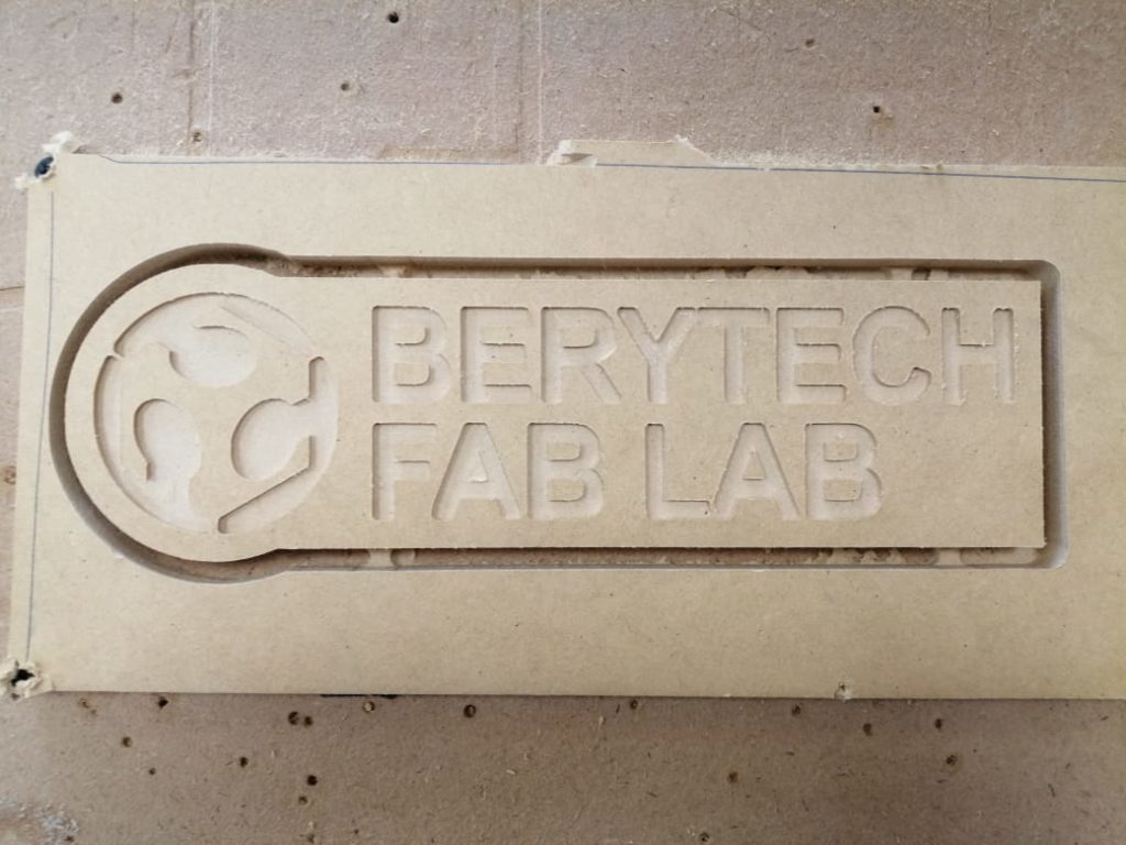
Milling Process
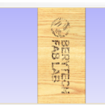
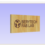
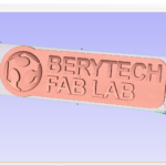
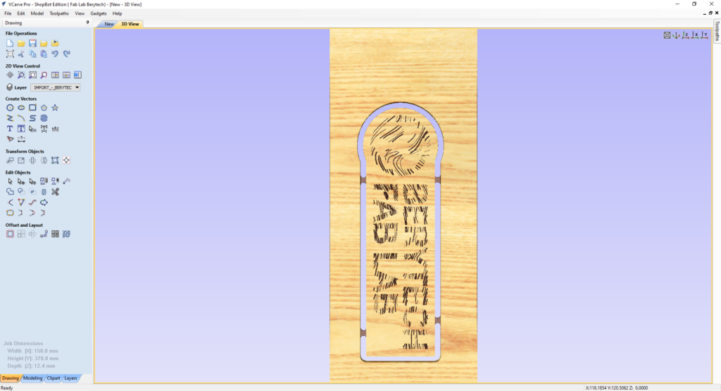
Final Results
-
V-Bit
To prepare the toolpath, follow the following steps:
- Select the “2D Profile Toolpath” button.
- Select the model outline as the vector followed for cutting.
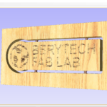
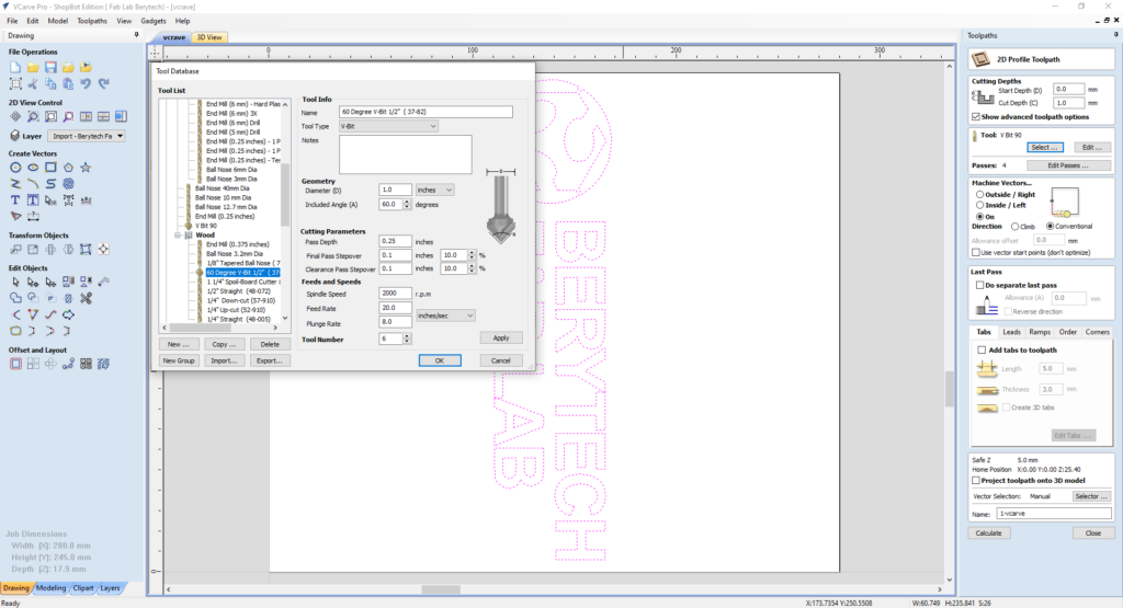
- Choose the Start Depth and Cut Depth. In this example we used 1mm, as a cut depth.
- Select the tool used for outline cutting. In this example, we used a 60 degrees V Bit.
- Choose your preferred machining tool position with respect to the chosen outline vector. In this example we choose the “On” option, so that the tool cut the material along the chosen vector.
When everything is set, press “Calculate”, to calculate your toolpath.
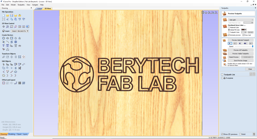
Select the “Preview Toolpath” button, to visualize the milling job, and make sure the results are as expected. If you notice any problems in the preview, make sure to go back and review all your settings to make sure that everything is running fine.
Once the toolpath is ready, save the toolpath files in your dedicated folder, and perform the milling job.
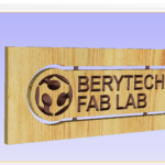
Milling Process
Final Results
Option 2: Pocket Toolpath
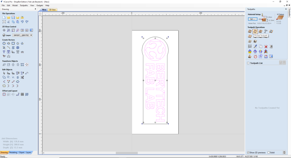
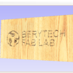
This option is used to remove large areas of material. It removes the areas contained inside the selected vectors at a certain chosen depth. The example below describe how Pocket Toolpath milling, or in other words, pocketing, is performed using a 3mm End Mill Bit.
To prepare the pocketing toolpath, follow the following steps:
- Select the “Pocket Toolpath” button.
- Select the logo outline as the vector to mill inside it.
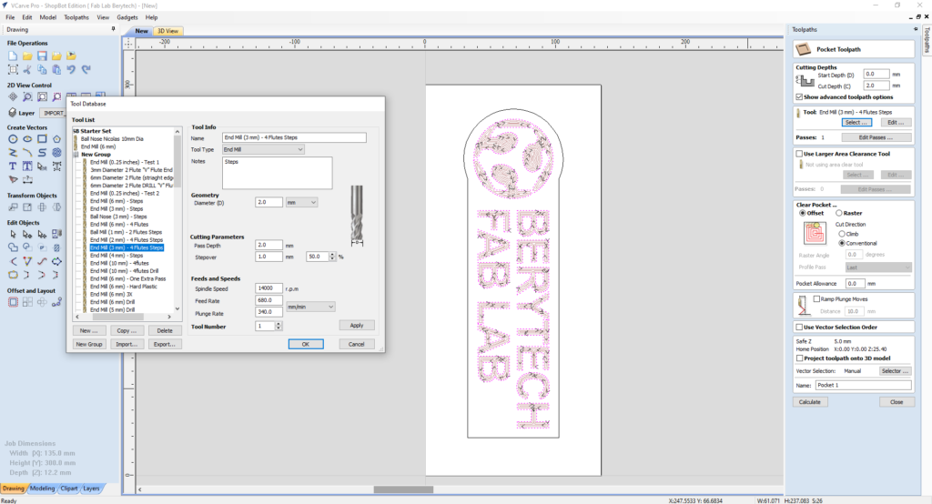
- Choose the Start Depth and Cut Depth. In this example we used 2 mm, as a cut depth.
- Select the tool used for outline cutting. In this example, we used a 3mm Diameter End Mill.
- Choose your preferred cut direction. You can choose either “Climb” or “Conventional”.
When everything is set, press “Calculate”, to calculate your toolpath.
Select the “Preview Toolpath” button, to visualize the milling job, and make sure the results are as expected. If you notice any problems in the preview, make sure to go back and review all your settings to make sure that everything is running fine.
To cut the part from the main block, profile toolpath milling is used. Please note that in this example, the part was cut from the main body using a Profile Toolpath milling from the outside of the outline vector. A 6mm End Mill bit was used for this part. Tabs were added to prevent to part from getting loose and to stay fixed in it’s location.
Again, select the “Preview Toolpath” button, to visualize the milling job, and make sure the results are as expected. If you notice any problems in the preview, make sure to go back and review all your settings to make sure that everything is running fine.
Once the toolpath is ready, save the toolpath files in your dedicated folder, and perform the milling job.
Milling Process
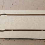
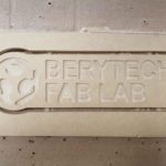
Final Results
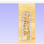
V-Carve/Engraving Toolpath
This option is used to remove large areas of material using a V-Bit. It removes the areas contained inside the selected vectors at a certain chosen Start depth and Flat Depth. Start Depth (D) specifies the depth at which the V-Carving toolpath is calculated, allowing V-Carving / Engraving to be machined inside a pocket region. When cutting directly into the surface of a job the Start Depth will usually be 0.0. The example below describe how V-Carve milling is performed using a 60 degrees V Bit.
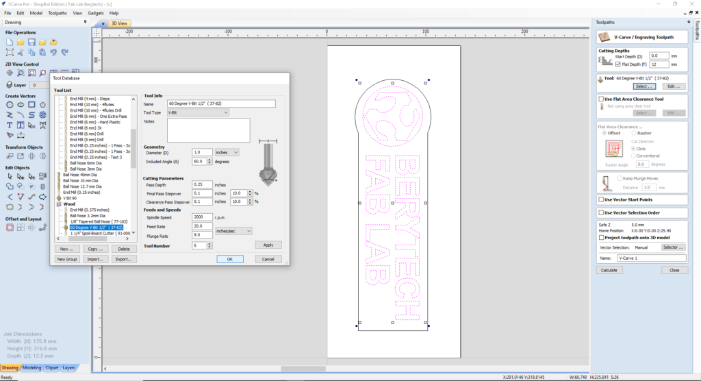
To prepare the pocketing toolpath, follow the following steps:
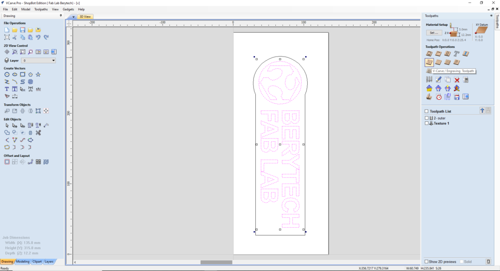
- Select the “V-Carve / Engraving Toolpath” button.
- Select the logo outline as the vector to mill inside it.
- Choose the Start Depth and Flat Depth. In this example we used 0 mm, as a start depth, and 12mm as a cut depth.
- Select the tool used for outline cutting. In this example, we used a 60 Degree V bit.
When everything is set, press “Calculate”, to calculate your toolpath.
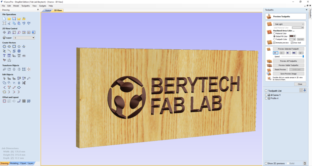
Select the “Preview Toolpath” button, to visualize the milling job, and make sure the results are as expected. If you notice any problems in the preview, make sure to go back and review all your settings to make sure that everything is running fine.
To cut the part from the main block, profile toolpath milling is used. Please note that in this example, the part was cut from the main body using a Profile Toolpath milling from the outside of the outline vector. A 6mm End Mill bit was used for this part. Tabs were added to prevent to part from getting loose and to stay fixed in it’s location.
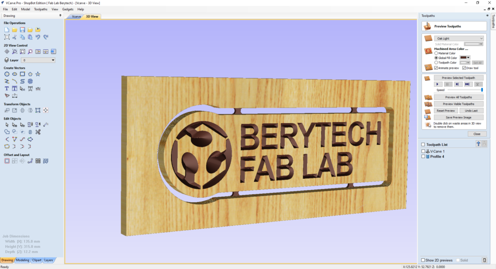
Again, select the “Preview Toolpath” button, to visualize the milling job, and make sure the results are as expected. If you notice any problems in the preview, make sure to go back and review all your settings to make sure that everything is running fine.
Once the toolpath is ready, save the toolpath files in your dedicated folder, and perform the milling job.
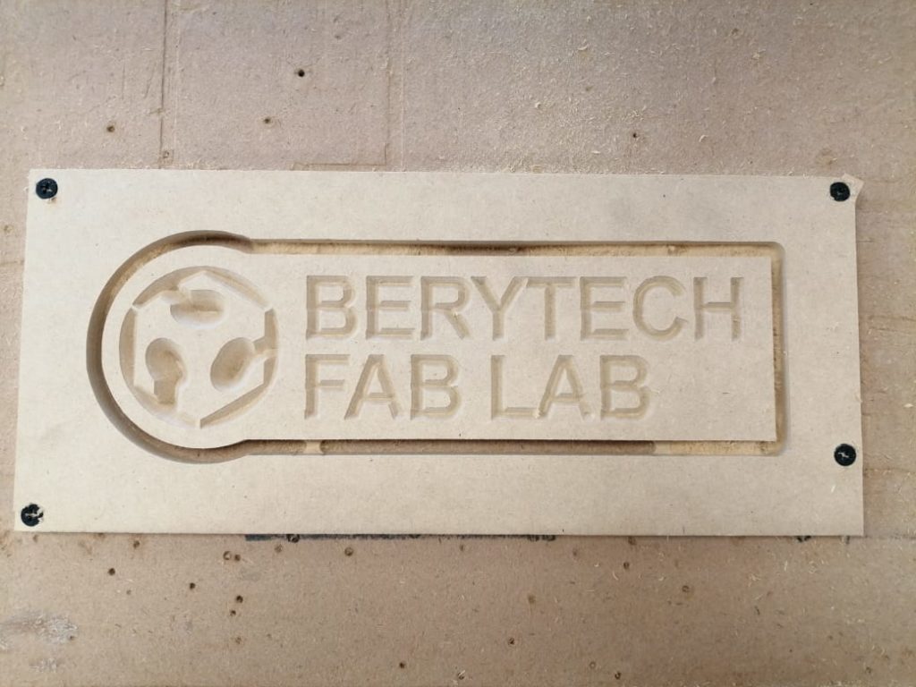
Milling Process
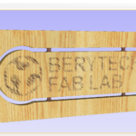
Final Results
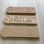
Texturing Toolpath
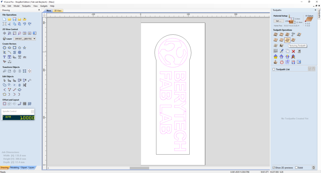
This option uses a specialized toolpath algorithm and the shape of the tool to generate a textured finish on the part. It removes the areas contained inside the selected vectors at a certain chosen depth, following an automated pattern, or a specific vector design. The examples below describe how Texturing Toolpath milling is performed using a 60 degrees V Bit, showing 3 different options that can be done.
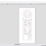
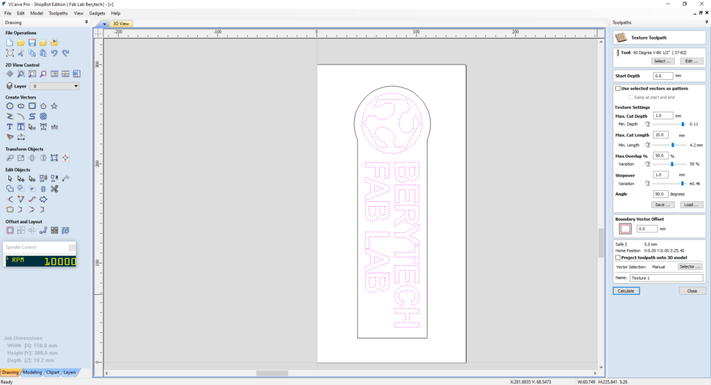
Texture Angle : 90 degrees
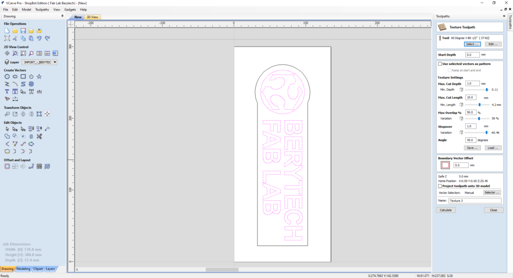
To prepare the texture toolpath, follow the following steps:
- Select the “Texture Toolpath” button.
- Select the logo outline as the vector to mill inside it.
- Choose the tool used for creating the texture. In this example a 60 Degree V-Bit was used.
- Choose the Start Depth. In this example we used used 0 mm, as a start depth.
- Choose your preferred Texture Settings. That include the Max Cut Depth, the Max Cut Length, the Max Overlap, Stepover and the Angle. In this example, The Max cut depth was 1mm, the Max Cut Length was 10mm, the Max Overlap was 50 %, Stepover was 1mm, and the Angle was 90 degrees.
- Choose Boundary Vector Offset if required. In this example the offset was 0.
When everything is set, press “Calculate”, to calculate your toolpath.
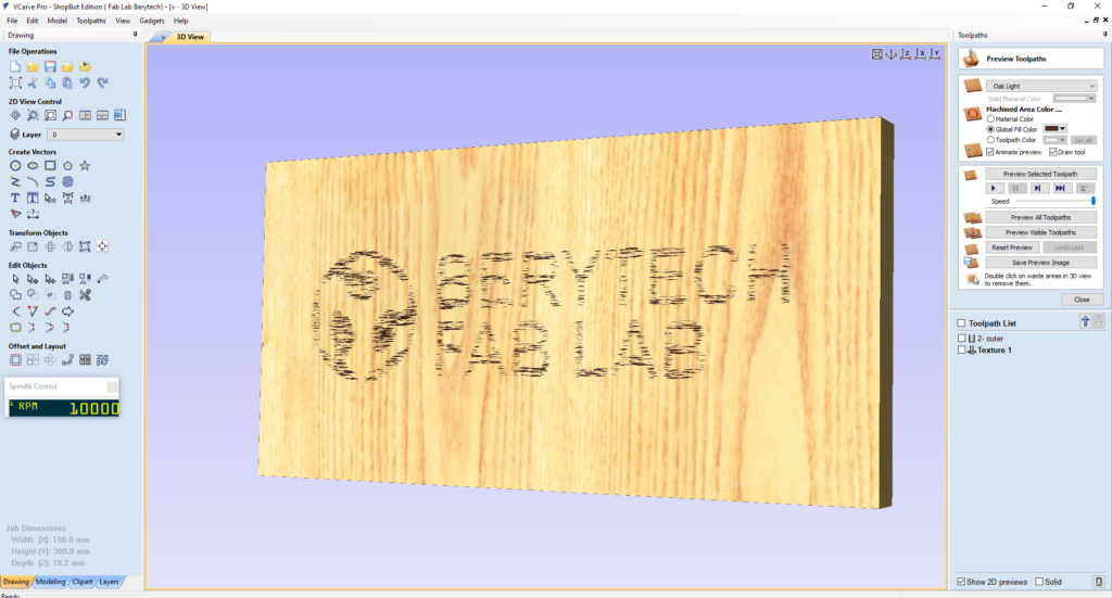
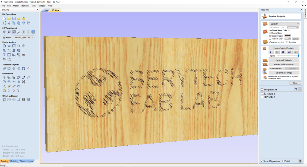
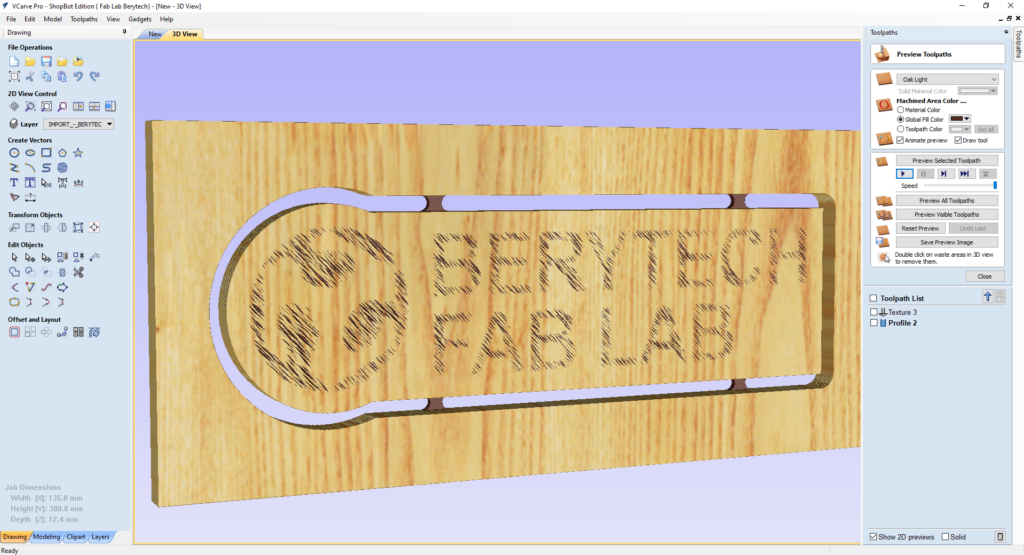
Select the “Preview Toolpath” button, to visualize the milling job, and make sure the results are as expected. If you notice any problems in the preview, make sure to go back and review all your settings to make sure that everything is running fine.
Please note that in this example, the part was cut from the main body using a Profile Toolpath milling from the outside of the outline vector using a 6mm End Mill bit
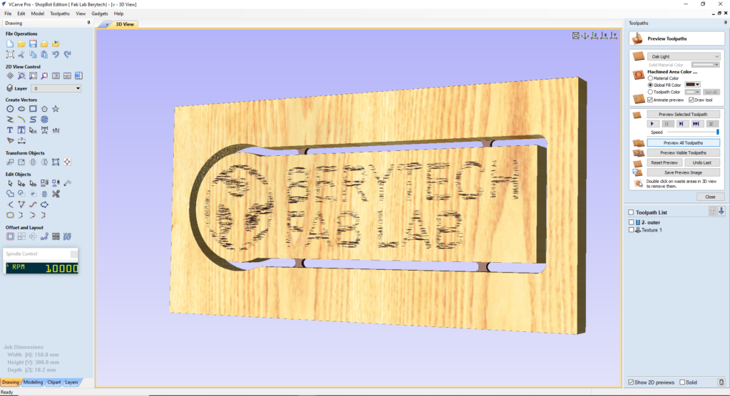
Once the toolpath is ready, save the toolpath files in your dedicated folder, and perform the milling job.
Milling Process
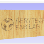
Final Results
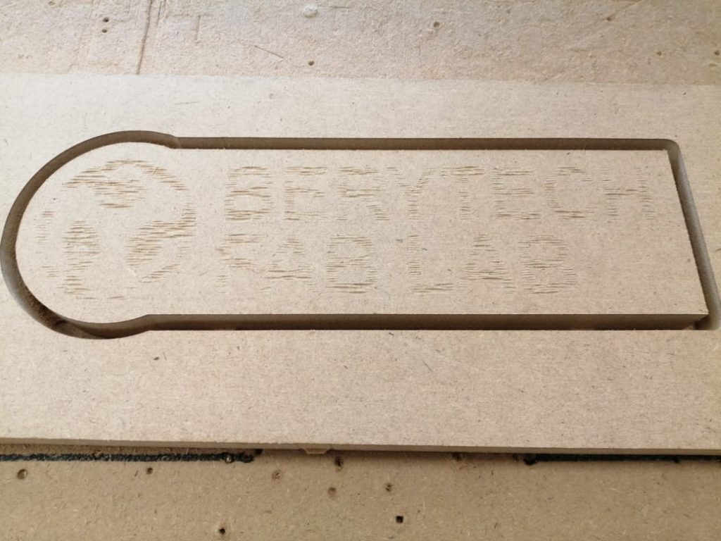
Texture Angle : 45 degrees
To prepare the texture toolpath, follow the following steps:
- Select the “Texture Toolpath” button.
- Select the logo outline as the vector to mill inside it.
- Choose the tool used for creating the texture. In this example a 60 Degree V-Bit was used.
- Choose the Start Depth. In this example we used used 0 mm, as a start depth.
- Choose your preferred Texture Settings. That include the Max Cut Depth, the Max Cut Length, the Max Overlap, Stepover and the Angle. In this example, The Max cut depth was 1mm, the Max Cut Length was 10mm, the Max Overlap was 50 %, Stepover was 1mm, and the Angle was 45 degrees.
- Choose Boundary Vector Offset if required. In this example the offset was 0.
When everything is set, press “Calculate”, to calculate your toolpath.
Select the “Preview Toolpath” button, to visualize the milling job, and make sure the results are as expected. If you notice any problems in the preview, make sure to go back and review all your settings to make sure that everything is running fine.
Please note that in this example, the part was cut from the main body using a Profile Toolpath milling from the outside of the outline vector using a 6mm End Mill bit
Once the toolpath is ready, save the toolpath files in your dedicated folder, and perform the milling job.
Milling Process
Final Results
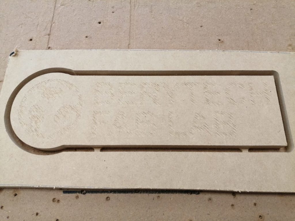
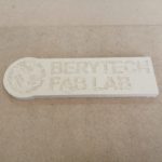
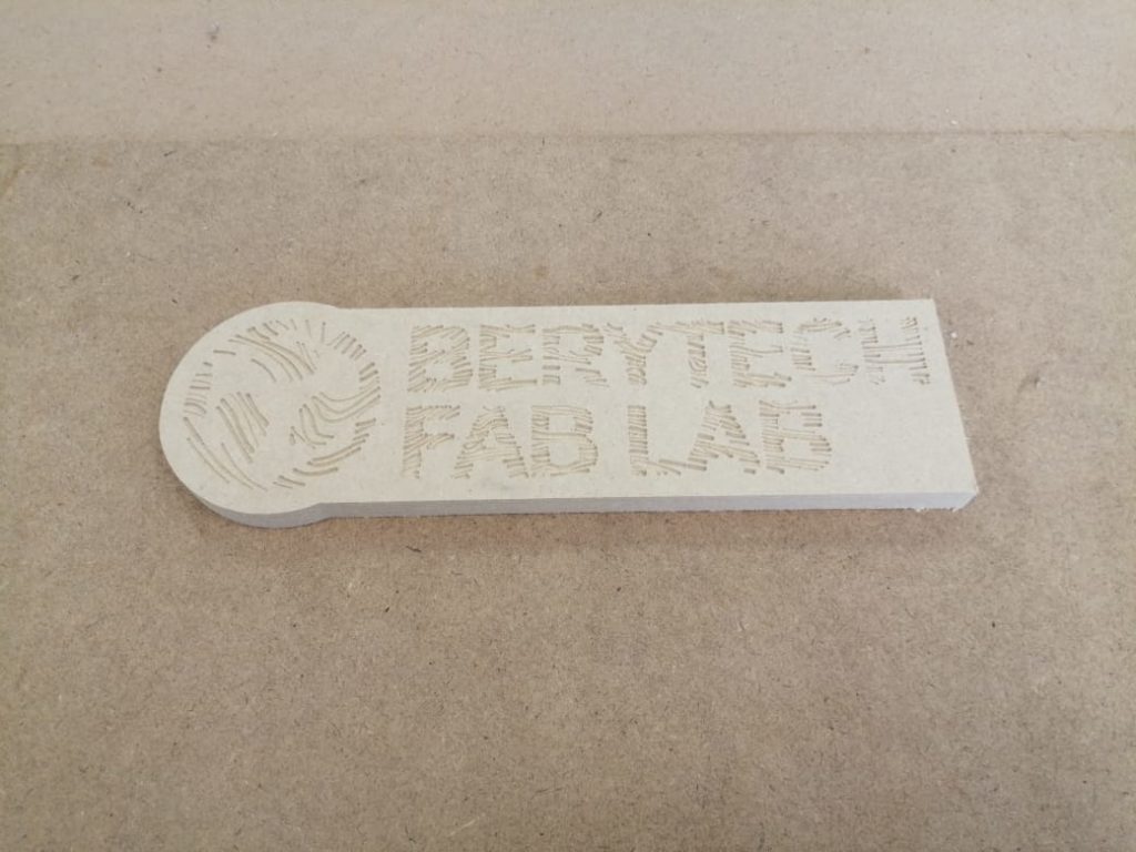
Texture with Selected Vectors
To prepare the texture toolpath, follow the following steps:
- Select the “Texture Toolpath” button.
- Select the logo outline as the vector to mill inside it.
- Choose the tool used for creating the texture. In this example a 60 Degree V-Bit was used.
- Choose the Start Depth. In this example we used used 0 mm, as a start depth.
- Select the “Use selected vectors as pattern” option and select the vectors.
- Choose your preferred Max Cut Depth. In this example, The Max cut depth was 1mm.
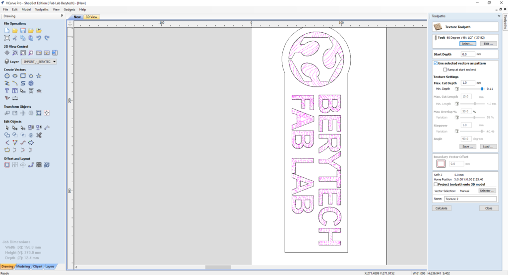
When everything is set, press “Calculate”, to calculate your toolpath.
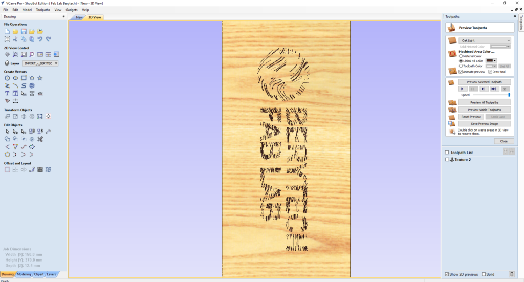
Select the “Preview Toolpath” button, to visualize the milling job, and make sure the results are as expected. If you notice any problems in the preview, make sure to go back and review all your settings to make sure that everything is running fine.
Please note that in this example, the part was cut from the main body using a Profile Toolpath milling from the outside of the outline vector using a 6mm End Mill bit
Once the toolpath is ready, save the toolpath files in your dedicated folder, and perform the milling job.
Milling Process
Final Results
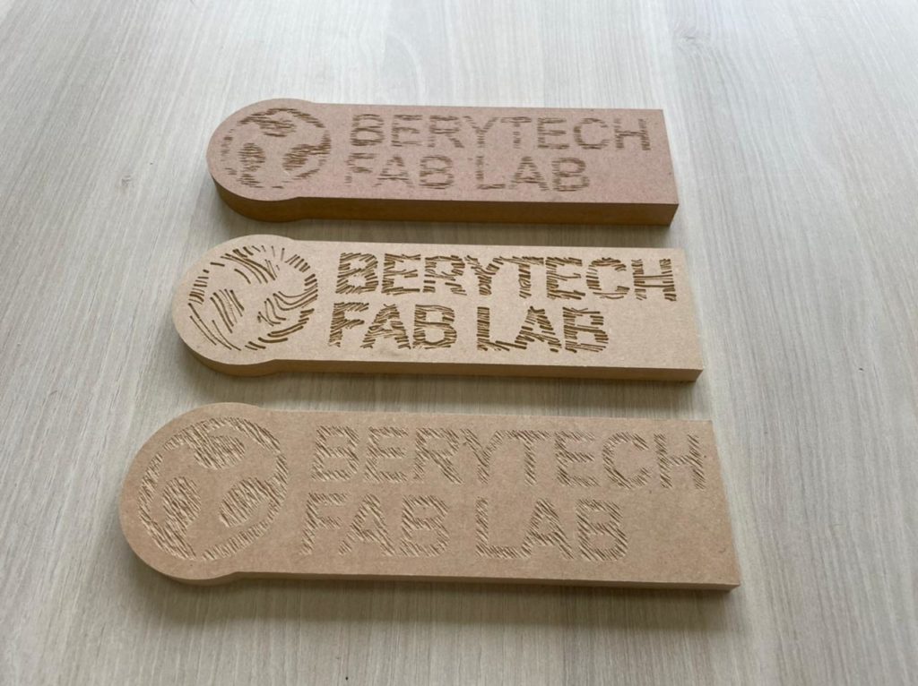
The image below illustrates the 3 different options of Texturing Toolpath that we tested, to visualize the difference between them.
Note: This document was written with the help of the V-Carve Software Manual found on the following Link