This section describes the different steps followed to produce a simple silhouette lamp of your own at the Fab Lab.
Step 1 : Designing the parts using Fusion 360
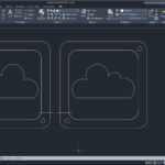
In order to produce a 3D object you first need to have its virtual design. This is to be done using any Computer Aided Design (CAD) software.
In this case we used fusion 360 to design the different parts.
The pieces were designed in a way that they are cut flat and then glued on top of each other to form a simple night stand lamp.
The final 3d model can be visualized below.
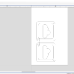
Step 2: Exporting Sketch to .DXF format
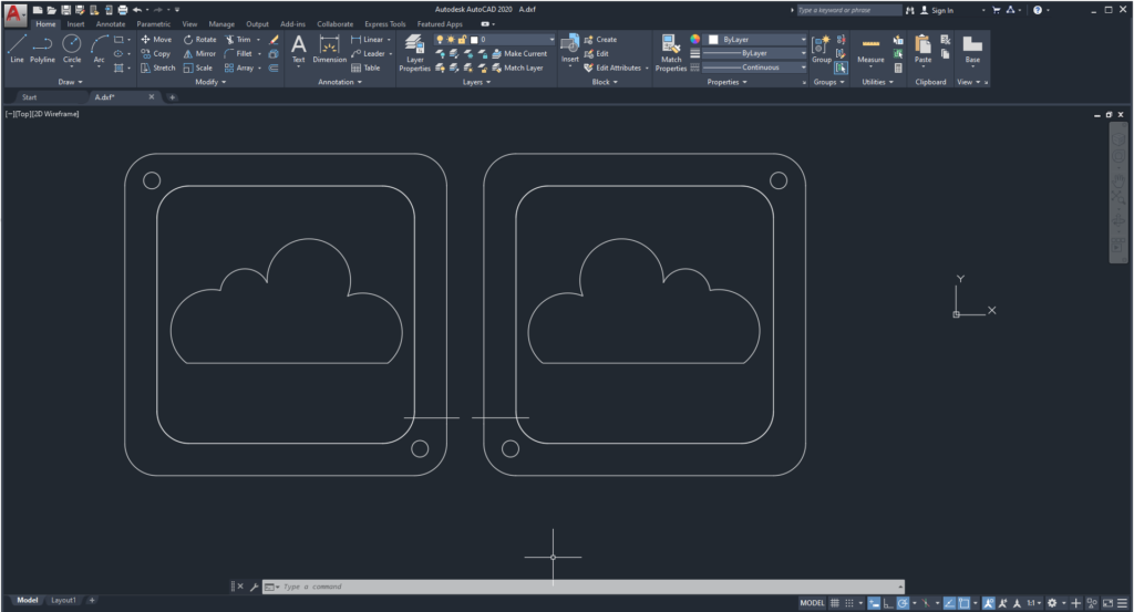
After finalizing the parametric design on Fusion 360, the next step was to extract the Sketch in .DXF format. This file will then be imported to the V-Carve Software.
Step 3: Preparing G-Code on V-Carve
After that, the next step was to prepare the g-code based on our design.
The steps to set up V-Carve are as follows:
3-a: Perform the Job Setup based on Material Dimensions
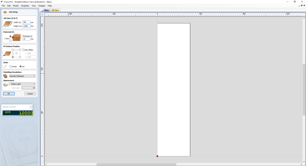
Start by setting up the dimensions of the material that you will be using. Take into consideration the lost area because of the screws used to fix the board:
- Enter the Width (x) & Height (y) for the material you are using.
- Enter the Thickness (z) for the material you are using.
- Choose the XY Datum position, which is the Zero position on the CNC machine.
When everything is set, press “OK”.
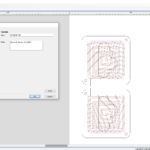
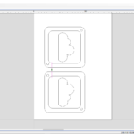
3-b: Import your 2D vector file and Choose the Best Orientation
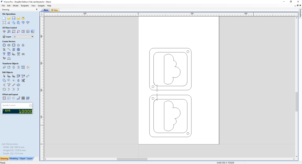
In order to generate the toolpath for the milling job, insert the dxf file into V-Carve as follows:
- Import the DXF file by selecting: “File” > “Import” > “Import Vectors” > Choose the 2D Model
- Move your design to your preferred position of the material you are milling.
When everything is set, press “OK”.
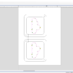
3-c: Prepare the Pocketing Toolpath
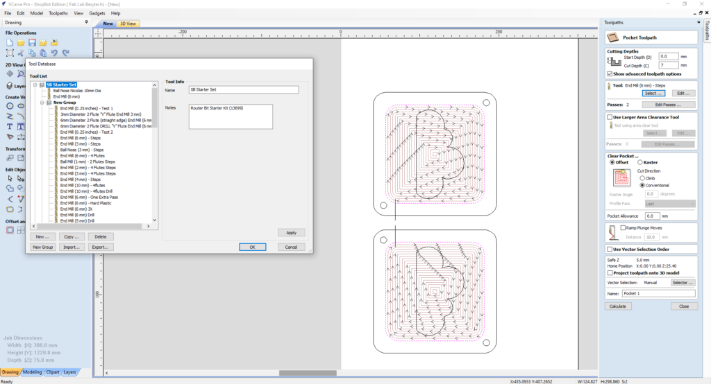
After setting the position of the model, prepare first the pocketing toolpath for the model:
- Select the “Pocket Toolpath” button
- Select the outline vector of the area you are planning to mill
- Select the tool used for roughing. In this example, we used a 6mm Diameter End Mill.
- Choose the Machining cut depth. In this example we choose the cut depth to be 7mm.
- Choose your preferred pocketing technique. You can use “offset” or “raster”. In this example we used the “offset” option.
- Add Ramps if needed, to reduce the load on the tool.
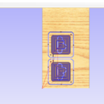
When everything is set, press “Calculate”, to calculate your toolpath.
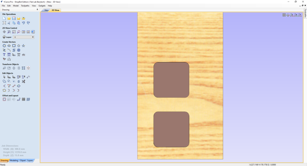
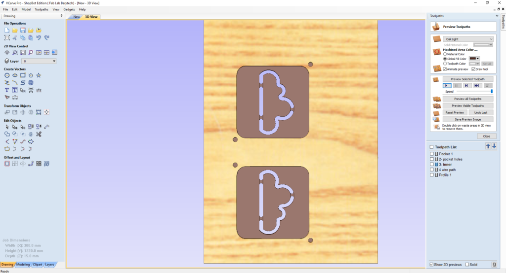
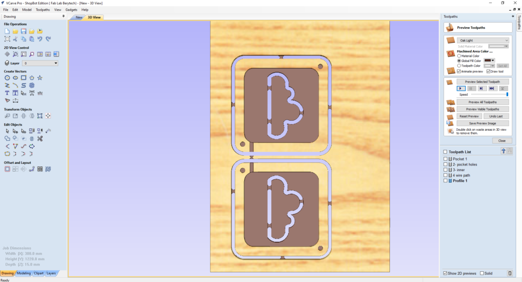
Select the “Preview Toolpath” button, to visualize the milling job, and make sure the results are as expected. The 3D preview mode also allows the job to be viewed in different material types with the option to paint the machined regions with a Fill Color. If you notice any problems in the preview, make sure to go back and review all your settings to make sure that everything is running fine.
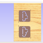
3-d: Prepare the Internal Profile Toolpath
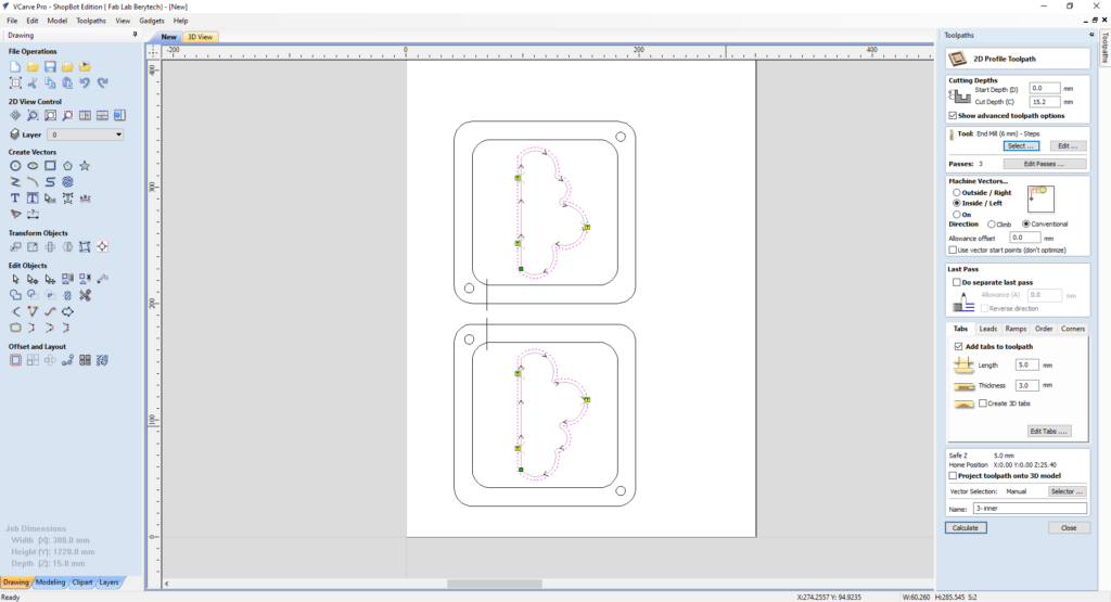
After setting the pocketing toolpath, prepare first the internal outline toolpath for the parts:
- Select the “2D Profile Toolpath” button.
- Select the vectors required for cutting.
- Choose the Start Depth and Cut Depth. In this example we used 18.1mm, as a cut depth, as the board we are using is 18mm thick.
- Select the tool used for outline cutting. In this example, we used a 6mm Diameter End Mill.
- Choose your preferred machining tool position with respect to the chosen outline vector. In this example we choose the “Inside” option, so that the tool cut the material inside the outline vector.
- Add tabs to the toolpath to keep the part in position and connected to the main body, to prevent it from moving and getting loose. Those tabs will be removed manually after milling to remove the part.
When everything is set, press “Calculate”, to calculate your toolpath.
Select the “Preview Toolpath” button, to visualize the milling job, and make sure the results are as expected. If you notice any problems in the preview, make sure to go back and review all your settings to make sure that everything is running fine.
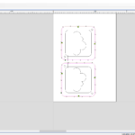
3-e: Prepare the Wire Passage Toolpath
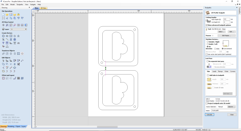
After preparing the internal outline toolpath, prepare the groove for the electric wire passage:
- Select the “2D Profile Toolpath” button.
- Select the vectors required for cutting.
- Choose the Start Depth and Cut Depth. In this example we used 3 mm, as a cut depth, as we only want to make a groove.
- Select the tool used for outline cutting. In this example, we used a 6mm Diameter End Mill.
- Choose your preferred machining tool position with respect to the chosen outline vector. In this example we choose the “On” option, so that the tool cut the material inside the outline vector.
- Add tabs to the toolpath to keep the part in position and connected to the main body, to prevent it from moving and getting loose. Those tabs will be removed manually after milling to remove the part.
When everything is set, press “Calculate”, to calculate your toolpath.
Select the “Preview Toolpath” button, to visualize the milling job, and make sure the results are as expected. If you notice any problems in the preview, make sure to go back and review all your settings to make sure that everything is running fine.

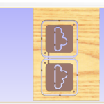
3-f: Prepare the External Profile Cutting Toolpath
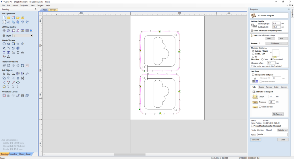
After preparing the Pocketing and Internal profile toolpaths, the last step is to cut the model from the material body. To do that, prepare the 2D profile toolpath for the model:
- Select the “2D Profile Toolpath” button.
- Select the model outline as the vector followed for cutting.
- Choose the Start Depth and Cut Depth. In this example we used 18.1mm, as a cut depth, as the board we are using is 18mm thick.
- Select the tool used for outline cutting. In this example, we used a 6mm Diameter End Mill.
- Choose your preferred machining tool position with respect to the chosen outline vector. In this example we choose the “Outside” option, so that the tool cut the material outside the outline vector.
- Add tabs to the toolpath to keep the part in position and connected to the main body, to prevent it from moving and getting loose. Those tabs will be removed manually after milling to remove the part.
When everything is set, press “Calculate”, to calculate your toolpath. Select the “Preview Toolpath” button, to visualize the milling job, and make sure the results are as expected. If you notice any problems in the preview, make sure to go back and review all your settings to make sure that everything is running fine.
3-g: Check the Total Machining Time
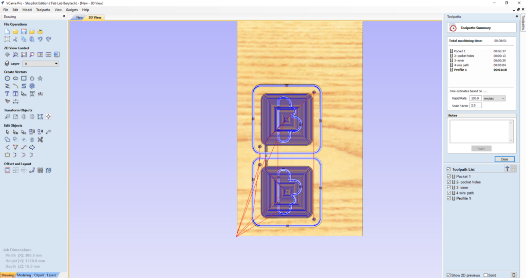
Check how long each machining toolpath will take, to estimate how much time it requires for production.
To do that, select the “Toolpaths Summary” button In this example, the whole milling process takes around 9 mins. Please note that the real production time includes the time that you take to fix the material, set the zero position for the machine, changing the milling bit between jobs, and removing the part once it is done.
3-h: Save the Toolpaths
After doing the pocketing and cutting toolpaths, save the toolpath files in your dedicated folder.
To do that, select the “Save Toolpath” button. This option allows toolpaths to be saved in the appropriate file format needed to drive the CNC machine.
Step 4: Preparing the CNC Machine and Zeroing the Tool Position
Next we need to set the zero position for the machine on the board we are using.
To do so, we need to follow those steps.
- Manually move the router to the desired X and Y position, and then zero the X and Y from the control panel
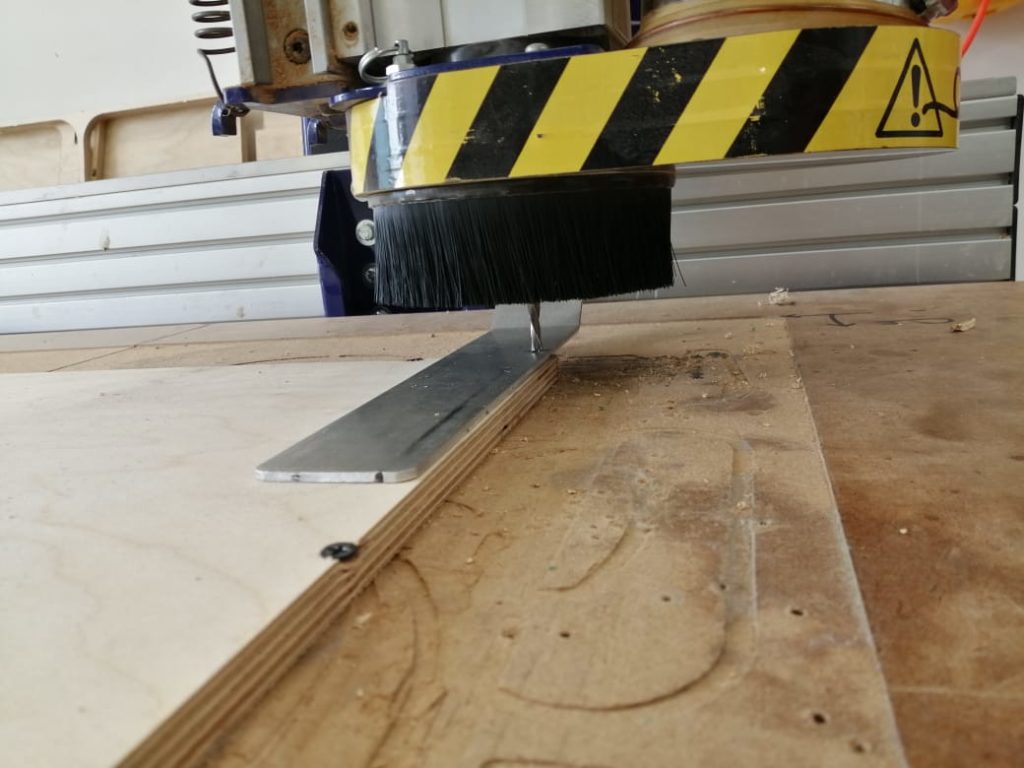
- Zero the Z-Axis using the automatic zeroing option on the Shopbot software. The plate is positioned under the router on the surface of the board, and the “Z-zero” button is selected. The process is fully automated
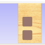
Step 5: Performing the Milling Job
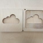
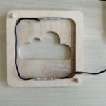
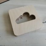
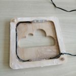
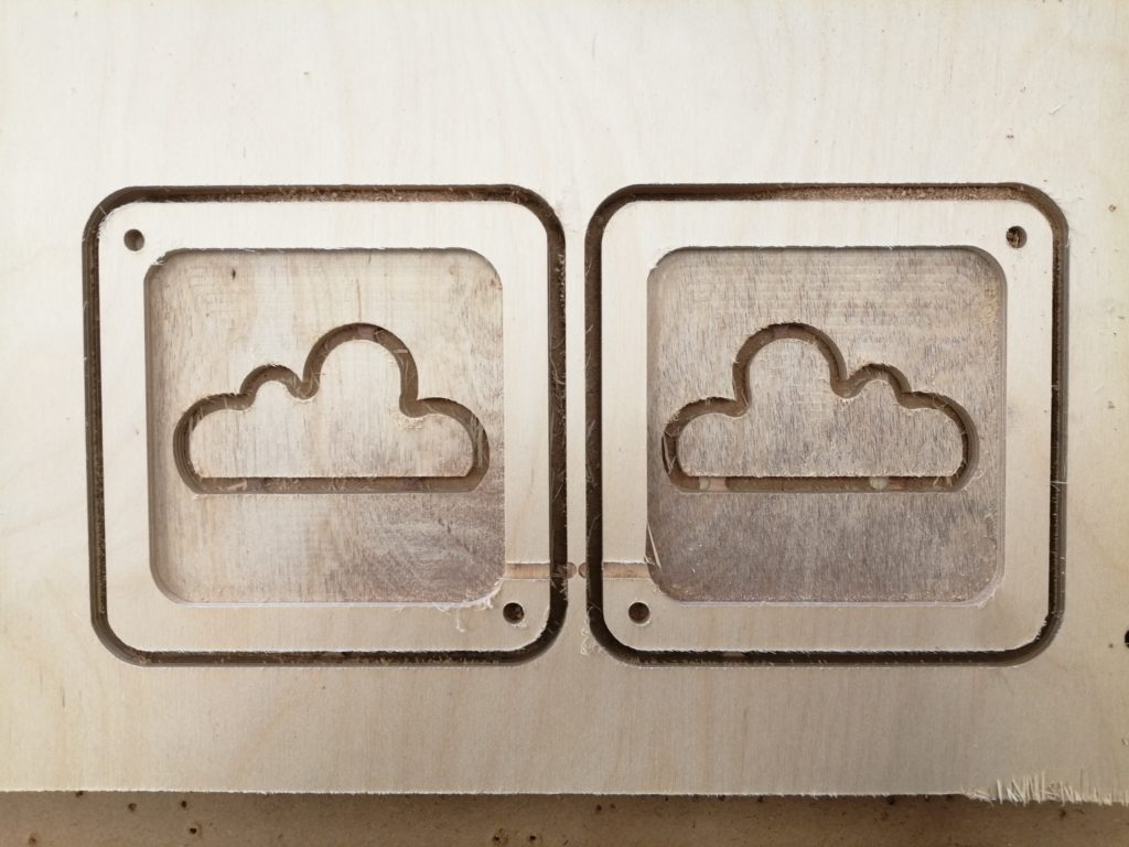
Next we perform the milling job. Just import the G-code to the Shopbot software and launch the job. The video illustrates the milling job. The final parts are shown below.
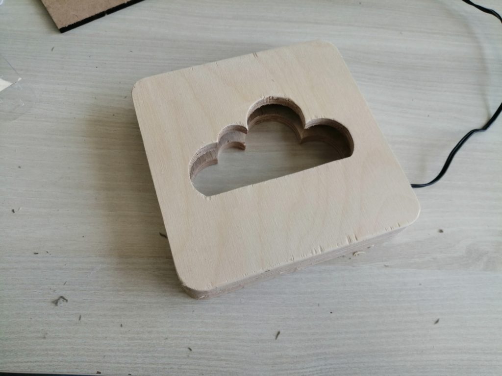
Step 6: Remove the Milled Parts and Clean them
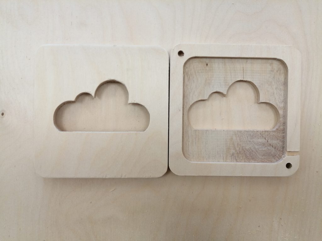
Once the parts are ready, cut all tabs using a Wood Chisel. After that clean the surface of the newly cut parts using a sand paper to remove any unwanted wood chips.
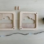
Step 7: Prepare all required components
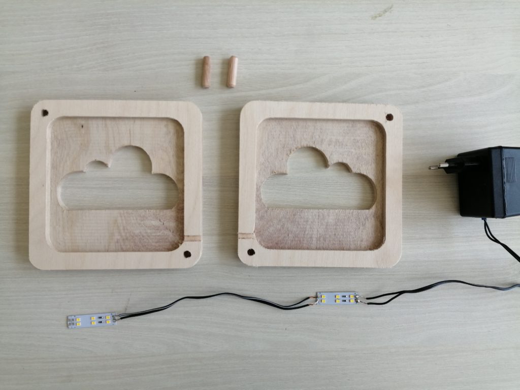
Prepare all the needed components to assemble you lamp. In this case, we needed wooden wedges to join both parts together without loosing precision. We also needed LED strips that we soldered directly to a 12V power supply. To turn on the lamp, you simply plug it in the wall.
Step 8: Assembling the pieces
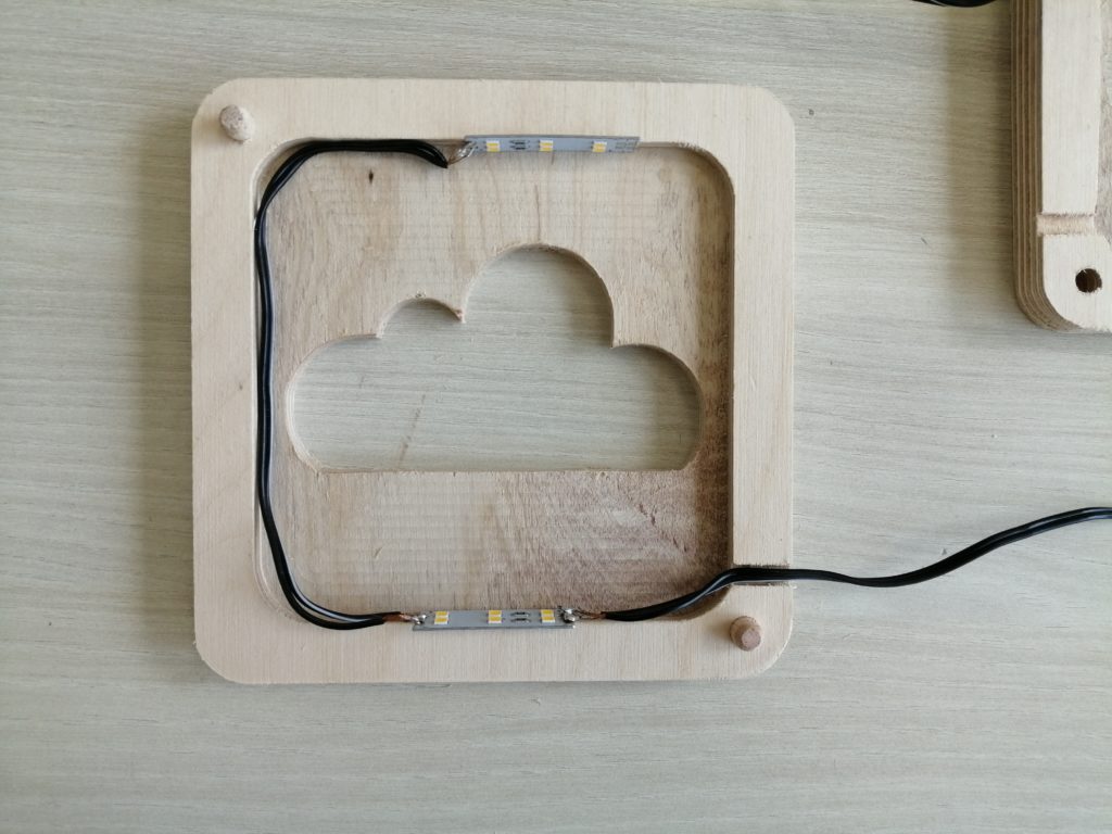
The final step is to assemble all the pieces together to form the lamp.
To do that, glue the different parts together using a wooden glue and with the help of some clamps, then wait for it to dry.
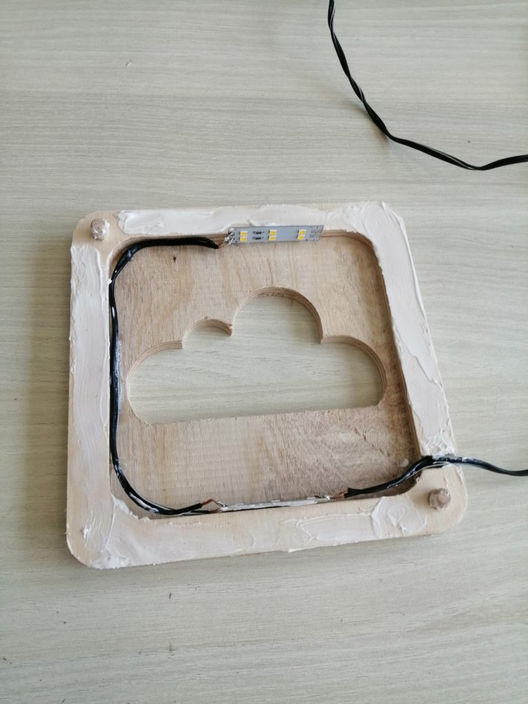
After that remove the wood clamps, and then remove any wood chips or extra glue using sand paper. Below you can see the final result.
Step 9: Plug it in and enjoy
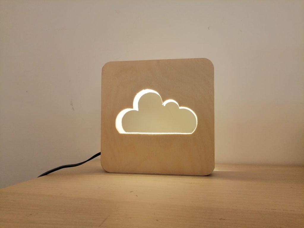
Finally, place your new lamp in your favorite spot and enjoy.