This section describes the different steps followed to produce an Arduino controlled maze game using various material produced by the help of Laser Cutting technology, and 3D printing. Those steps show how you can combine multiple materials and electronics to produce a fun project.
Step – 1 : Designing The Parts Using Fusion 360
In order to 3D print and Laser Engrave and Cut any object, you need to have its digital design. This is to be done using any Computer Aided Design (CAD) software. In this example, The maze mechanism and parts were designed on Fusion 360, a CAD (Computer Aided Design) software. You can use any software of your choice.
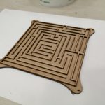
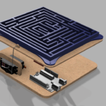
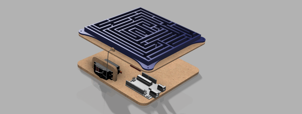
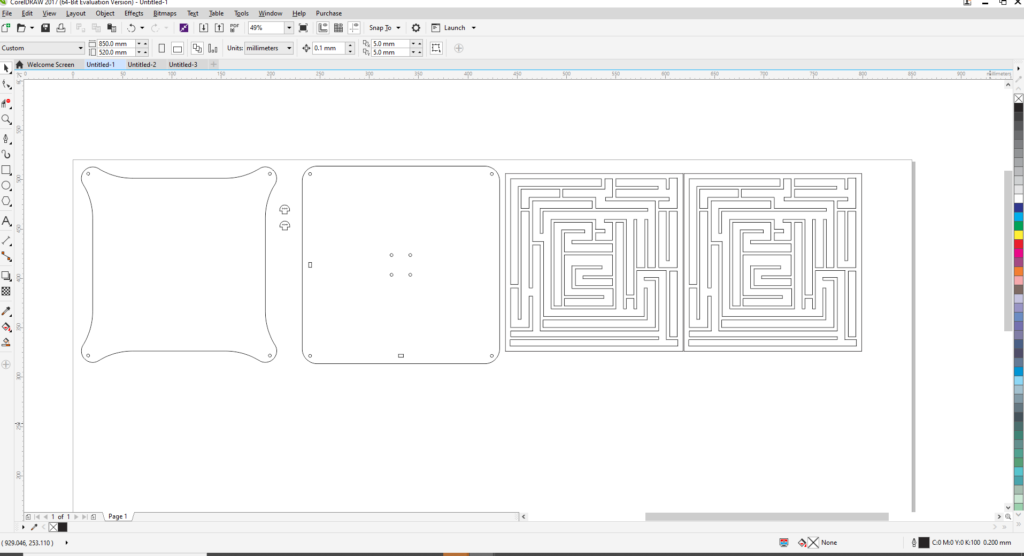
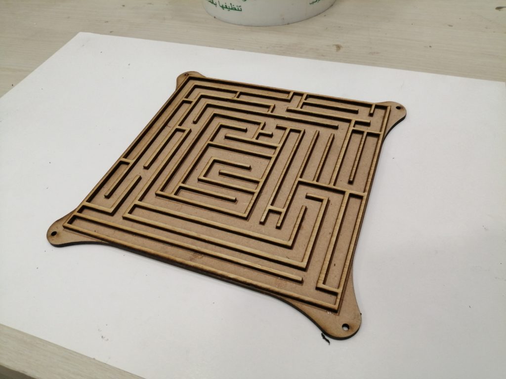
The pieces were designed to be produced on a laser cutter using multiple material (mainly wood), and the ball joint mechanism was designed to be 3D printed.
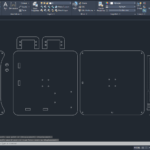
The final design can be seen in the image below.
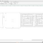
Step – 2: Save Design In DXF Format And Import To AutoCad
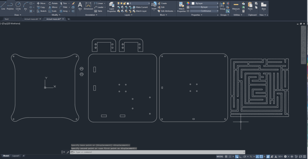
To prepare the Laser Engraving Cutting job, you need a 2D vector file. To do that, export the Sketches from Fusion 360 (save sketch in .DXF format) and then open in AutoCad.
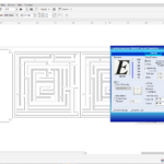
Step – 3: Import Design & Prepare Your File for the Laser Engraving & Cutting Job
To prepare the Laser Cutting job, you should open the digital design file in a preparation software and choose the best settings that would achieve the best final result. In this example, we used Corel Draw as a preparation software.
- Import the digital design file into CorelDraw by selecting “File” > “Import” > Choose you file from location.
- Choose Your Material: Typically you may have an idea about what kind of material you will use before you laser cut. This is very important to choose the best settings required for the chosen material. Preferred settings for different material can be found in the Machine’s Catalogue. Best settings are usually chosen based on experience and previous tests done. In this example we will be using 3mm MDF and 6mm MDF for the base.
- Select the outline as “Hair Line”: We select “hair line” for the lines that we want to be cut, in our case the outline circles, and we select “ none “ for the objects that we want to engrave.
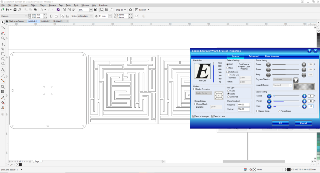
- Choose Job Type: “Combined” was selected, as we are both engraving and cutting in this example.
- Choose Your Cutting Parameters: The next step is then deciding on the different parameters for engraving (Raster Settings) and cutting (Vector Settings). We have to choose the best settings we need to have the best result. There are different variables that affect the final product coming out of the Laser Cutter. Among those variables are the Power, Speed, and DPI. In this example the following settings were used:
- Vector Settings 3mm: Speed: 6%, Power: 40%, Frequency: 10
- Vector Settings 6mm: Speed: 3%, Power: 40%, Frequency: 10
- Forward the Job: After choosing all the variables, send the order to the laser cutter. But before pressing Play on the Laser cutter, we have to manually set it up the printer with respect to the material we intend to use.
Step – 4: Set Up The Laser Cutter
After preparing the file and the relative settings we need, the next step is to place the material we want in the laser cutter and set it up according to the thickness of the material.
To cut and engrave on our laser cutter, the following procedure was followed:
- Set the focus of the laser using the V shaped Gauge.
- Set the zero position of the laser on the top left corner of the Acrylic sheet.
- Turn On the Air compressor and ventilators .
Step – 5: Perform the Engraving & Cutting job
Press the play button on the laser cutter, and voila, it starts cutting.
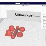
Step – 6: Slicing – Preparing The File For 3D Printing
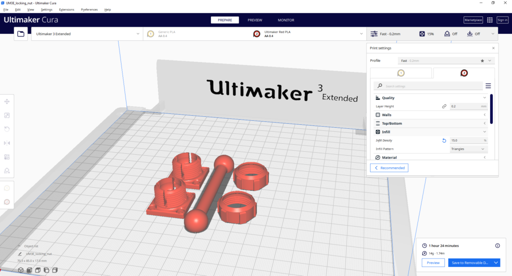
The STL file is then imported into a slicing software, like Cura. Choose the settings that are needed to have a successful print.
- Choose Your Material: Typically you may have an idea about what kind of material you will use before you print. There are many different 3D printing materials available, and you can choose them based on the properties that you want your object to have. In this project PLA filaments were used.
- Choose Your Parameters: The next step is then deciding on the different parameters of your object and the printing process. This includes deciding on the size and placement of your print. The layer thickness chosen was 0.2mm which produces a normal surface finish. The infill chosen was 15% which is enough for the small parts we are producing. No support where required in this print.
The slicing software will then convert the information from the STL file into a G-code, which is a specific code containing exact instructions for the printer.
Step 7: 3D printing
This is when the magic happens! The printer will create the object layer by layer. Depending on the size of your object, your printer, and the materials used, the job can be done in a matter of minutes or over several hours.
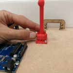
Once the print is done, remove the printed part from the printer’s printing bed after it cools down.
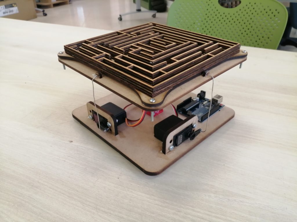
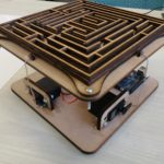
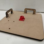
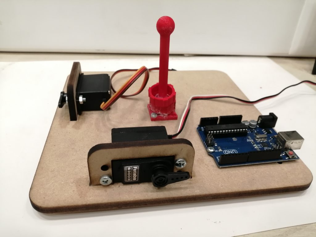
Step 8: Assemble all required components
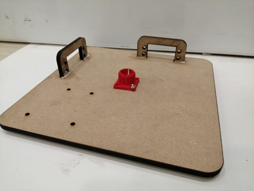
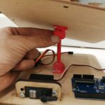
Prepare all the needed components to assemble the maze. In this case, we needed wooden parts cut on the laser cutter and 3D printed parts. We also needed Servo motors, and a joy stick to control the movement. all parts will then be connected and controlled by an Arduino board.
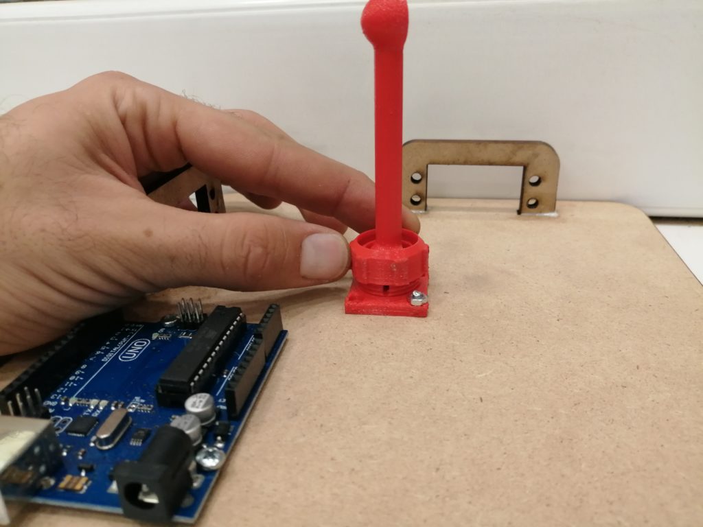
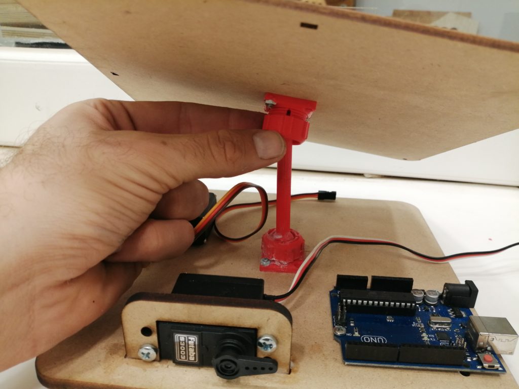
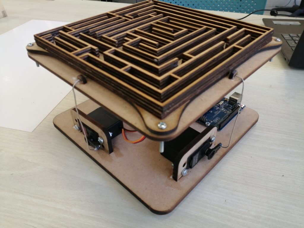
You can use paper clips to connect the servo motors to the top plate.
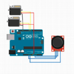
Step 8: Assemble all pieces, Connect your Arduino Uno board to your computer and upload your code
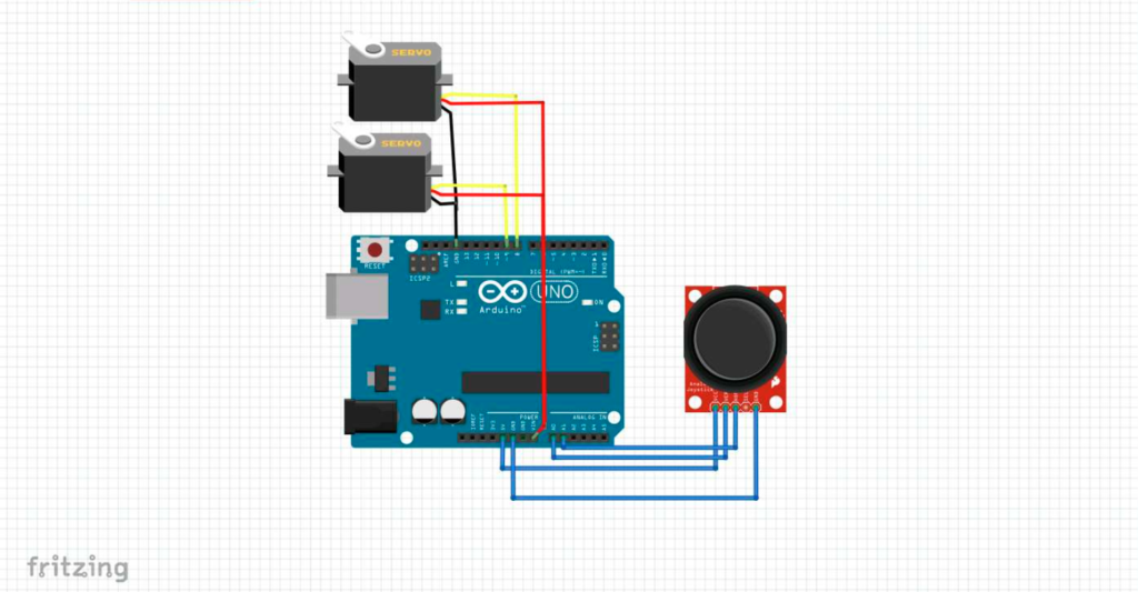
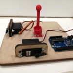
Connect your components to Arduino as the in the image, notice that we connect servo motors to “Vin” because we will use use an external 12 volts to power the servo motors.
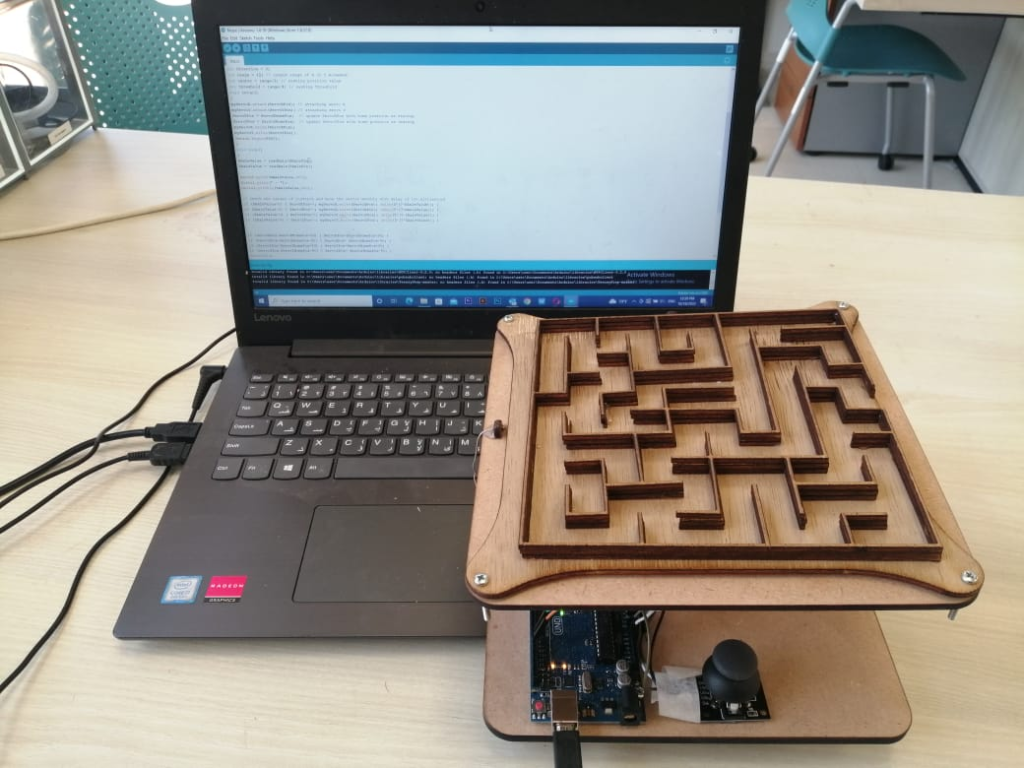
In order to control the motors, a code was prepare on the Arduino IDE. The code reads the value of the joy stick, and commands the motors accordingly.
Before connecting Arduino to your PC, remove the Vin that is connected on Arduino from servo motors, reconnect after uploading the code.
You can find the full code below
#include <Servo.h>Servo myServoX; // define servo motor for X-axisServo myServoY; // define servo motor for Y-axisint ServoXPin = 8; // define X-axis pinint ServoYPin = 9; // define Y-axis pinint ServoXHomePos =90; // set home position for servosint ServoYHomePos =90;int ServoXPos =103;int ServoYPos =90;int XAxlePin = A0; // define X-axis pin control for joystick A0int YAxlePin = A1; // define Y-axis pin control for joystick A1int XAxleValue = 0; // set start up value for joystickint YAxleValue = 0;int Direction = 0;int range = 12; // output range of X or Y movementint center = range/2; // resting position valueint threshold = range/4; // resting thresholdvoid setup(){myServoX.attach(ServoXPin); // attaching servo XmyServoY.attach(ServoYPin); // attaching servo YServoXPos = ServoXHomePos; // update ServoXPos with home position as startupServoYPos = ServoYHomePos; // update ServoYPos with home position as startupmyServoX.write(ServoXPos);myServoY.write(ServoYPos);Serial.begin(9600);}void loop(){XAxleValue = readAxis(XAxlePin);YAxleValue = readAxis(YAxlePin);Serial.print(XAxleValue,DEC);Serial.print(” – “);Serial.println(YAxleValue,DEC);// check the values of joystick and move the servos smothly with delay of 100 millisecondif (XAxleValue>0) { ServoXPos++; myServoX.write(ServoXPos); delay(5*(7-XAxleValue)); }if (XAxleValue<0) { ServoXPos–; myServoX.write(ServoXPos); delay(5*(7+XAxleValue)); }if (YAxleValue>0) { ServoYPos++; myServoY.write(ServoYPos); delay(5*(7-YAxleValue)); }if (YAxleValue<0) { ServoYPos–; myServoY.write(ServoYPos); delay(5*(7+YAxleValue)); }if (ServoXPos>ServoXHomePos+90) { ServoXPos=ServoXHomePos+90; }if (ServoXPos<ServoXHomePos-90) { ServoXPos= ServoXHomePos-90; }if (ServoYPos>ServoYHomePos+90) { ServoYPos=ServoYHomePos+90; }if (ServoYPos<ServoYHomePos-90) { ServoYPos= ServoYHomePos-90; }delay(10);}int readAxis(int thisAxis) {// read the analog input:int reading = analogRead(thisAxis);// map the reading from the analog input range to the output range:reading = map(reading, 0, 1023, 0, range);// if the output reading is outside from the// rest position threshold, use it:int distance = reading – center;if (abs(distance) < threshold) {distance = 0;}// return the distance for this axis:return distance;}
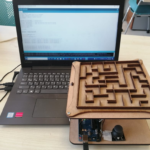
Step 9: Plug it in and enjoy
You can change the top plate and make new maze shapes whenever you want !!