This section describes the different steps followed to produce the Fab Lab entrance sign. Those steps can be followed to produce any custom sign for your office or house.
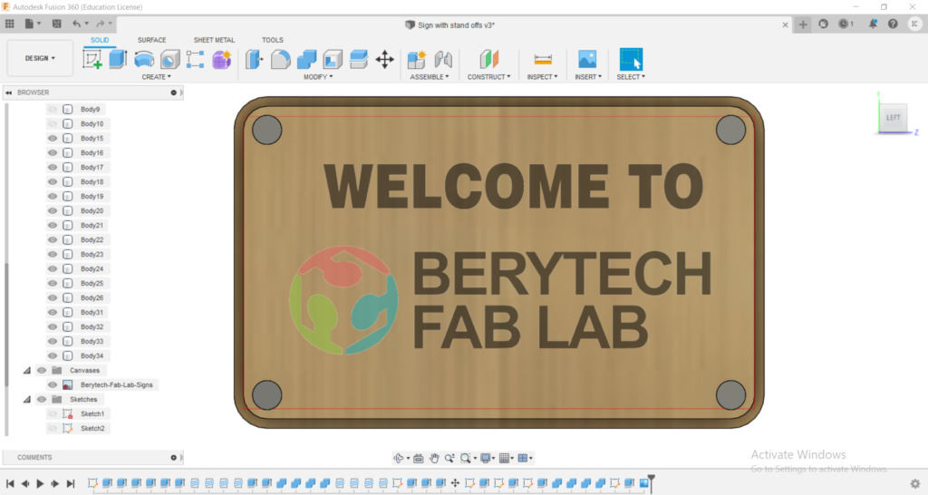
Step 1 : Designing the part using Fusion 360
In order to produce a 3D object you first need to have its virtual design. This can be done using any Computer Aided Design (CAD) software.
In this case we used fusion 360 to design the different parts.
The pieces were designed to be produced using multiple digital fabrication technologies: CNC Milling, Laser Cutting, Vinyl Printing & Cutting and 3D Printing.
The final 3d model can be visualized below.
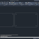
Step 2: Exporting Sketch to .DXF format
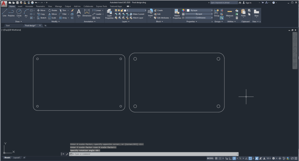
After finalizing the parametric design on Fusion 360, the next step was to extract the parts’ Sketched in .DXF format. This file will then be imported to the V-Carve Software to prepare to CNC milling job, and into Corel Draw to prepare for the Laser Cutting job.
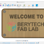
Step 3: Preparing G-Code on V-Carve
After that, the next step was to prepare the g-code based on our design.
The steps to set up V-Carve are as follows:
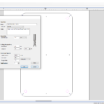
3-a: Perform the Job Setup based on Material Dimensions
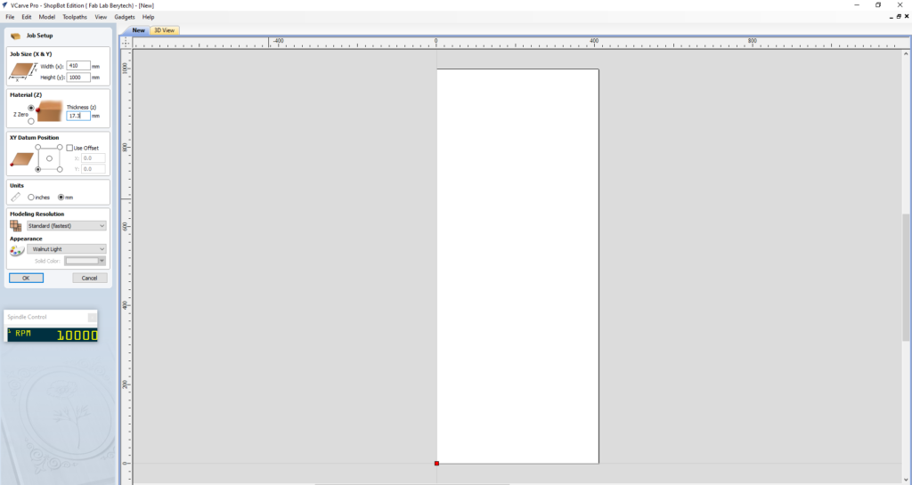
Start by setting up the dimensions of the material that you will be using. Take into consideration the lost area because of the screws used to fix the board:
- Enter the Width (x) & Height (y) for the material you are using.
- Enter the Thickness (z) for the material you are using.
- Choose the XY Datum position, which is the Zero position on the CNC machine.
When everything is set, press “OK”.
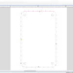
3-b: Import your 2D vector file and Choose the Best Orientation
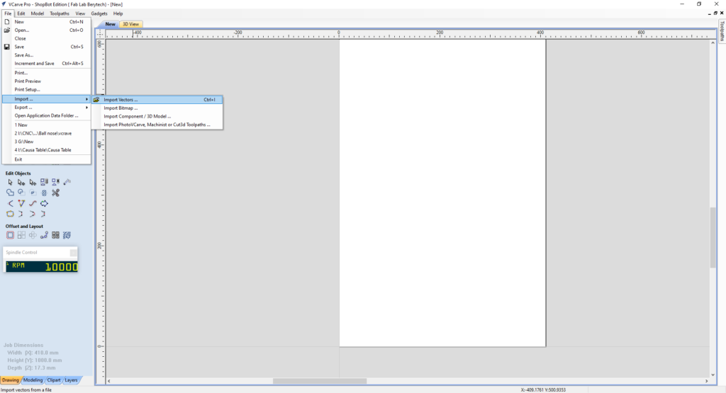
In order to generate the toolpath for the milling job, insert the dxf file into V-Carve as follows:
- Import the DXF file by selecting: “File” > “Import” > “Import Vectors” > Choose the 2D Model
- Move your design to your preferred position of the material you are milling.
When everything is set, press “OK”.
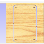
3-c: Prepare the Pocketing Toolpath
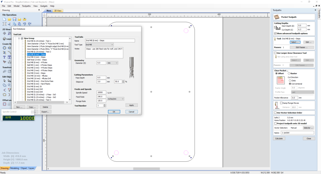
After setting the position of the model, prepare first the pocketing toolpath for the model:
- Select the “Pocket Toolpath” button
- Select the tool used for roughing. In this example, we used a 6mm Diameter End Mill.
- Choose the Machining cut depth. In this example we choose the cut depth to be 6.3mm.
- Choose your preferred pocketing technique. You can use “offset” or “raster”. In this example we used the “offset” option.
- Add Ramps if needed, to reduce the load on the tool.
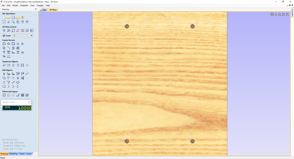
When everything is set, press “Calculate”, to calculate your toolpath.
Select the “Preview Toolpath” button, to visualize the milling job, and make sure the results are as expected. The 3D preview mode also allows the job to be viewed in different material types with the option to paint the machined regions with a Fill Color. If you notice any problems in the preview, make sure to go back and review all your settings to make sure that everything is running fine.
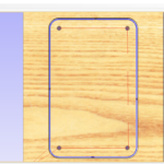
3-d: Prepare the External Profile Cutting Toolpath
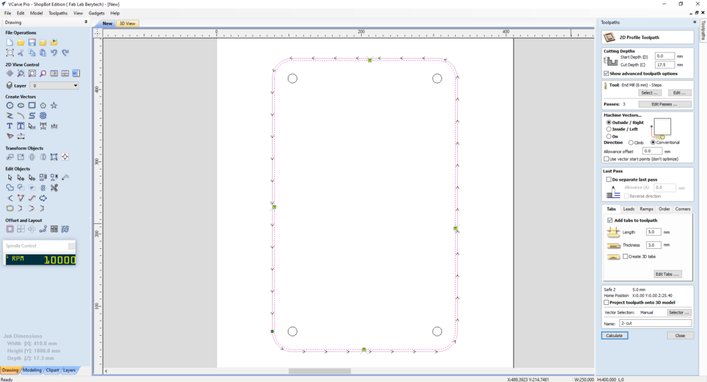
After preparing the Pocketing and Internal profile toolpaths, the last step is to cut the model from the material body. To do that, prepare the 2D profile toolpath for the model:
- Select the “2D Profile Toolpath” button.
- Select the model outline as the vector followed for cutting.
- Choose the Start Depth and Cut Depth. In this example we used 18.1mm, as a cut depth, as the board we are using is 18mm thick.
- Select the tool used for outline cutting. In this example, we used a 6mm Diameter End Mill.
- Choose your preferred machining tool position with respect to the chosen outline vector. In this example we choose the “Outside” option, so that the tool cut the material outside the outline vector.
- Add tabs to the toolpath to keep the part in position and connected to the main body, to prevent it from moving and getting loose. Those tabs will be removed manually after milling to remove the part.
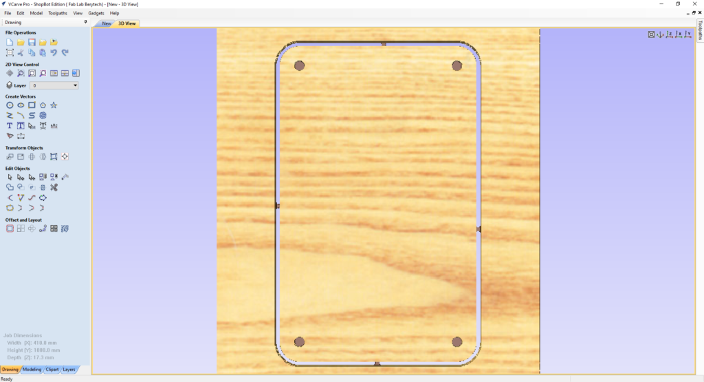
When everything is set, press “Calculate”, to calculate your toolpath. Select the “Preview Toolpath” button, to visualize the milling job, and make sure the results are as expected. If you notice any problems in the preview, make sure to go back and review all your settings to make sure that everything is running fine.
3-f: Check the Total Machining Time
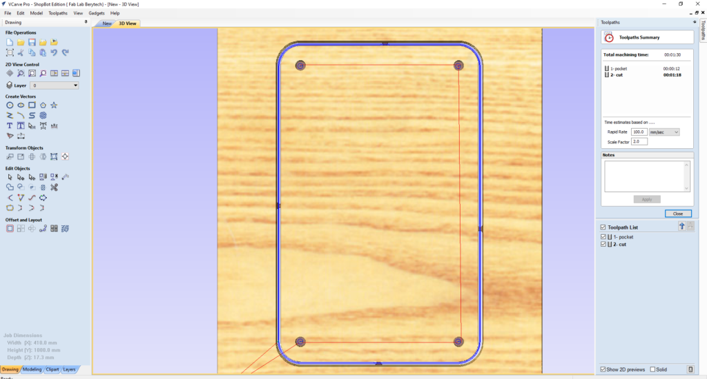
Check how long each machining toolpath will take, to estimate how much time it requires for production.
To do that, select the “Toolpaths Summary” button In this example, the whole milling process takes around 1.5 mins. Please note that the real production time includes the time that you take to fix the material, set the zero position for the machine, changing the milling bit between jobs, and removing the part once it is done.
3-g: Save the Roughing and Smoothing Toolpath
After doing the roughing, smoothing and cutting toolpaths, save the toolpath files in your dedicated folder.
To do that, select the “Save Toolpath” button. This option allows toolpaths to be saved in the appropriate file format needed to drive the CNC machine.
Step 4: Preparing the CNC Machine and Zeroing the Tool Position
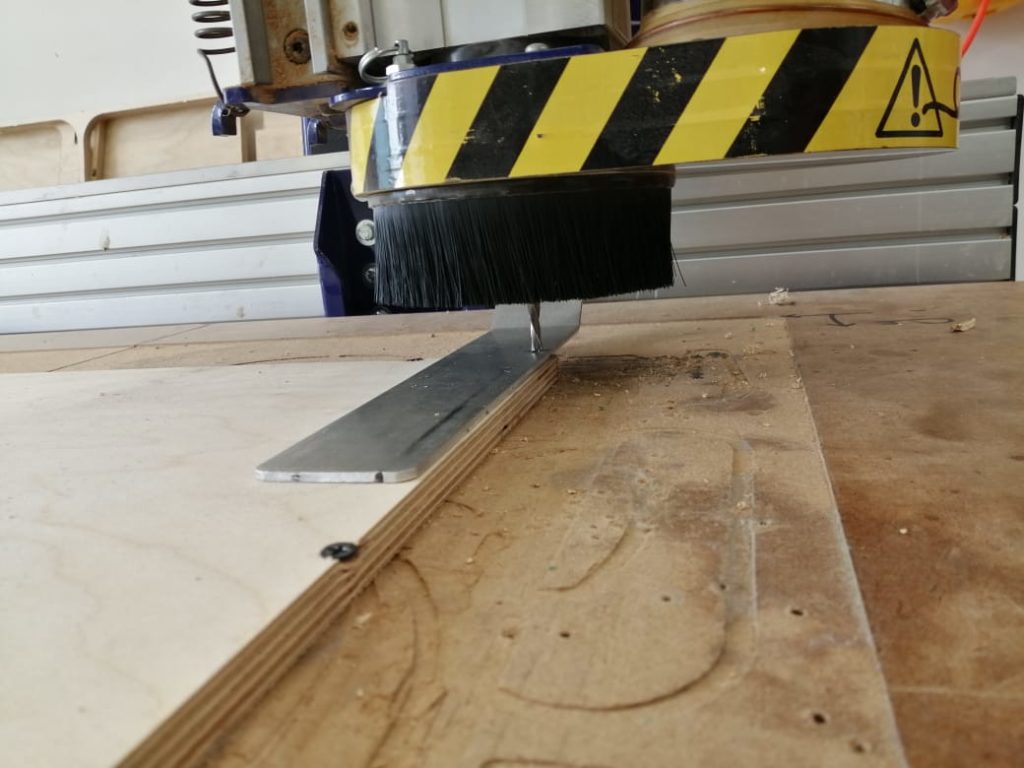
Next we need to set the zero position for the machine on the board we are using.
To do so, we need to follow those steps.
- Manually move the router to the desired X and Y position, and then zero the X and Y from the control panel
- Zero the Z-Axis using the automatic zeroing option on the Shopbot software. The plate is positioned under the router on the surface of the board, and the “Z-zero” button is selected. The process is fully automated
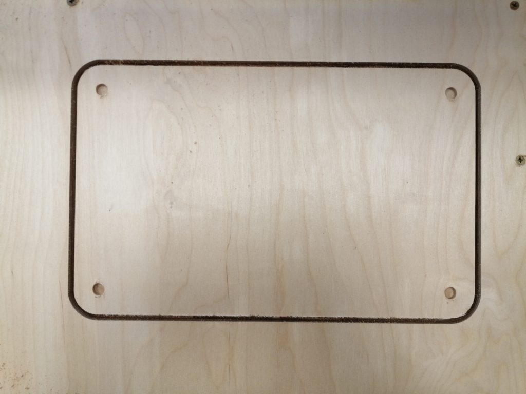
Step 5: Performing the Milling Job
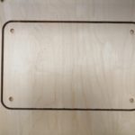
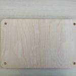
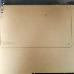
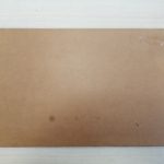
Next we perform the milling job. Just import the G-code to the Shopbot software and launch the job. The video illustrates the milling job. The final parts are shown below.
Step 6: Remove the Milled Parts
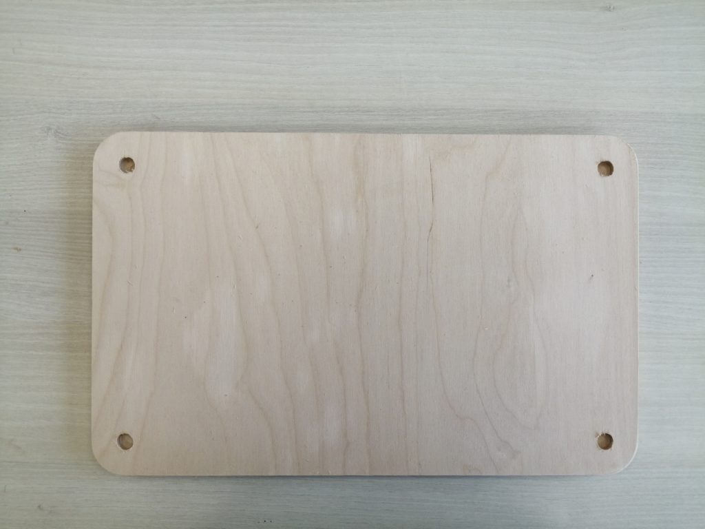
Once the parts are ready, cut all tabs using a Wood Chisel. After that clean the surface of the newly cut parts using a sand paper to remove any unwanted wood chips.
Step – 7: Prepare Your File For Laser Cutting
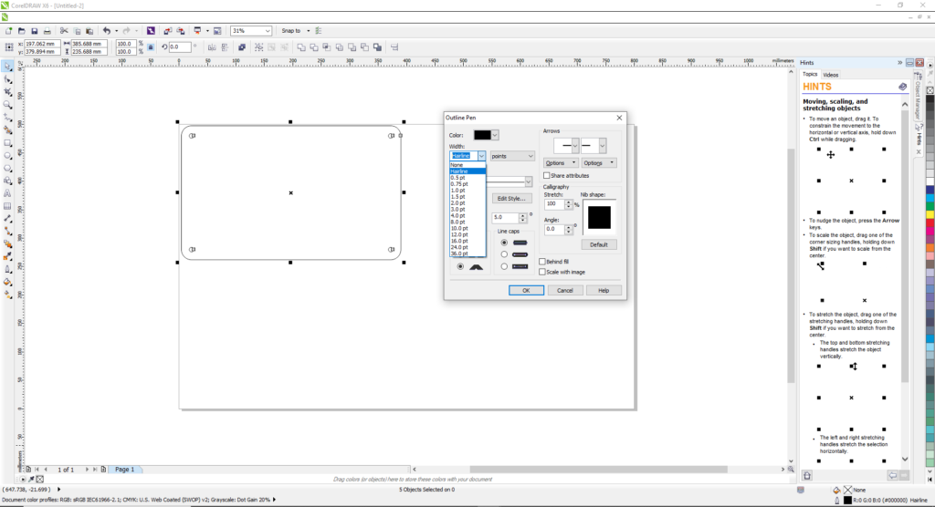
To prepare the Laser Cutting job, you should open the digital design file in a preparation software and choose the best settings that would achieve the best final result. In this example, we used Corel Draw as a preparation software.
- Import the digital design file into CorelDraw by selecting “File” > “Import” > Choose you file from location.
- Choose Your Material: Typically you may have an idea about what kind of material you will use before you laser cut. This is very important to choose the best settings required for the chosen material. Preferred settings for different material can be found in the Machine’s Catalogue. Best settings are usually chosen based on experience and previous tests done. In this example we will be using 6mm Acrylic board.
- Choose Job Type: “Vector” was selected, as we are only cutting in this example.
- Choose Your Cutting Parameters: The next step is then deciding on the different parameters for cutting, the “Vector Settings”. We have to choose the best settings we need to have the best result. There are different variables that affect the final product coming out of the Laser Cutter. Among those variables are the Power and Speed. In this example the following settings were used: Speed: 6%, Power: 100%, Frequency: 10
- Forward the Job: After choosing all the variables, send the order to the laser cutter. But before pressing Play on the Laser cutter, we have to manually set it up the printer with respect to the material we intend to use.
Step – 8: Setting Up The Laser Cutter
After preparing the file and the relative settings we need, the next step is to place the material we want in the laser cutter and set it up according to the thickness of the material.
To cut and engrave on our laser cutter, the following procedure was followed:
- Set the focus of the laser using the V shaped Gauge.
- Set the zero position of the laser on the top left corner of the Acrylic sheet.
- Turn On the Air compressor and ventilators .
Step – 9: Perform The Cut
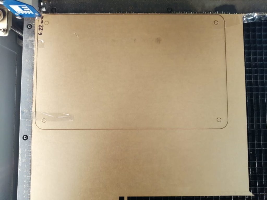
This is when the magic happens!
Press the play button on the laser cutter, and voila, it starts cutting.
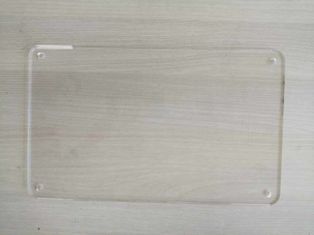
Step – 10: Remove Your Part
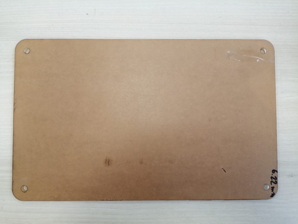
Remove the parts from the cutting bed after it cools down and all the fumes are sucked out of the machine.
Next, carefully remove the film from the acrylic sheet.
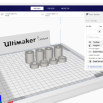
Step 11: Slicing – Preparing The File For 3D Printing
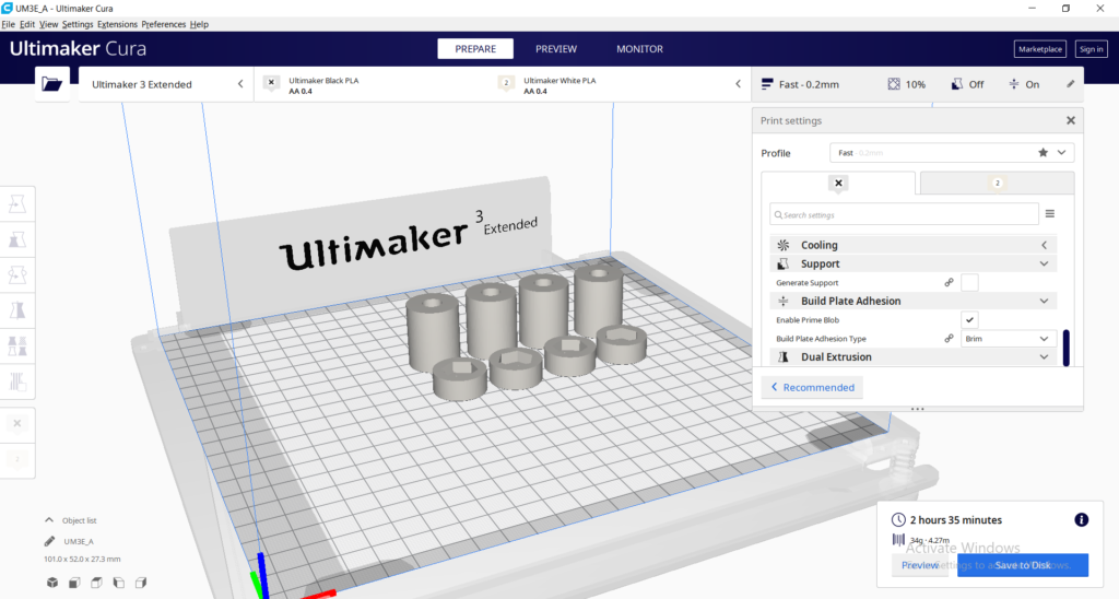
The STL file is then imported into a slicing software, like Cura. Choose the settings that are needed to have a successful print.
- Choose Your Material: Typically you may have an idea about what kind of material you will use before you print. There are many different 3D printing materials available, and you can choose them based on the properties that you want your object to have. In this project PLA filaments were used.
- Choose Your Parameters: The next step is then deciding on the different parameters of your object and the printing process. This includes deciding on the size and placement of your print. The layer thickness chosen was 0.15mm which produces a normal surface finish. The infill chosen was 20% which is enough for a small planter. No support where required in this print.
The slicing software will then convert the information from the STL file into a G-code, which is a specific code containing exact instructions for the printer.
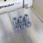
Step 12: 3D Printing
The printer will create the object layer by layer. Depending on the size of your object, your printer, and the materials used, the job can be done in a matter of minutes or over several hours.
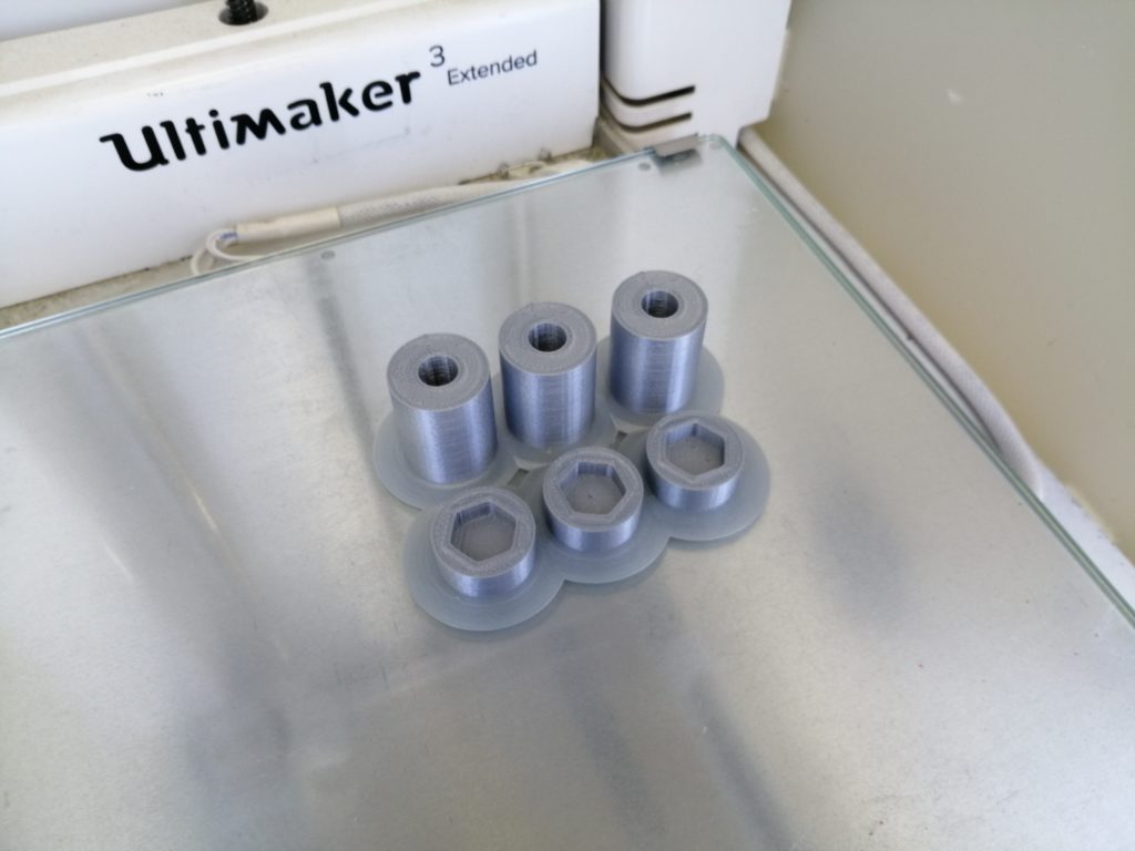
Step 13: Remove Your Print
Remove the printed part from the printer’s printing bed after it cools down.
Depending on what you want your final product to be or the material you used, there may be additional post-processing steps after printing, like painting, brushing off powder, etc. In this example the brim was removed from the printed part.
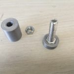
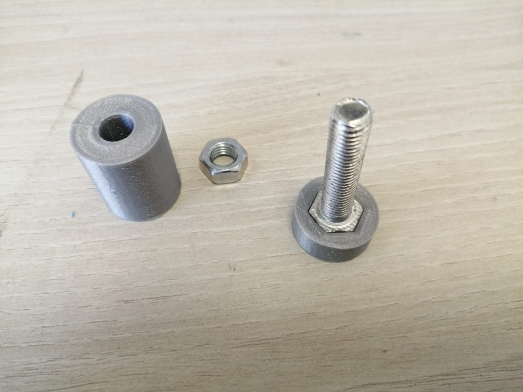
Parts were then tested to check its fitting with the intended nuts and bolts we want to use.
Step – 14 : Prepare the Design you want to print
In order to print and cut any sticker, you need to prepare the digital file first that you want to use for production. This could be a graphical vector file designed on any digital design software such as Adobe Illustrator, Corel Draw, GIMP and many more. It can also be simply an image that you like and you want to print and cut. Below is a brief guide to walk you through the design process.
- Choose Your Size & Shape : The first aspect of your design to think of is the size and shape of your sticker. This mainly depends on the intended use of the sticker, and where you are planning to stick it. The most common shapes for stickers are regular rectangular, squared, or circular designs. Make sure to consider the limitations of the machine you will be using. Most machines have a limited size and length that they can handle.
- Choose Your Best Typography: If your sticker is intended to communicate a message, it is very important to decide on the right choice of typography when designing your sticker. The main goal is to make sure that the message is readable by the intended audience, and to create brand visibility. It is advised that you choose a bold and clear typeface that can be read from a distance.
- Incorporate Your Brand: If your sticker represents and brand, it is important that the brand stays at the heart of your design. The main aim of a promotional sticker is to increase brand visibility, so unless your sticker well represents that brand, it is going to cause an undesired impact. It is always a good idea to include your logo in the sticker, as it is usually the most recognizable visual identity.
- Include a Call-To-Action: A call to action is usually a line of text or an image that prompts the recipient to take a specific course of action. This can be anything from visiting your website, following your social media profiles or give you a call.
- Keep Things Simple & To-The-Point: While a lot of information might be appropriate for leaflets, brochures or flyers, Stickers on the other hand should be as minimalistic and simple as possible.
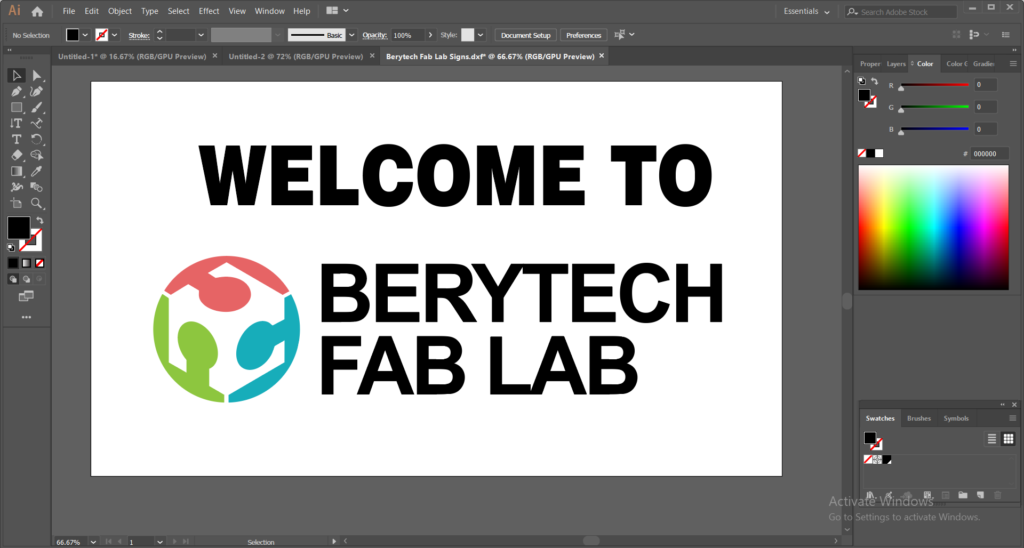
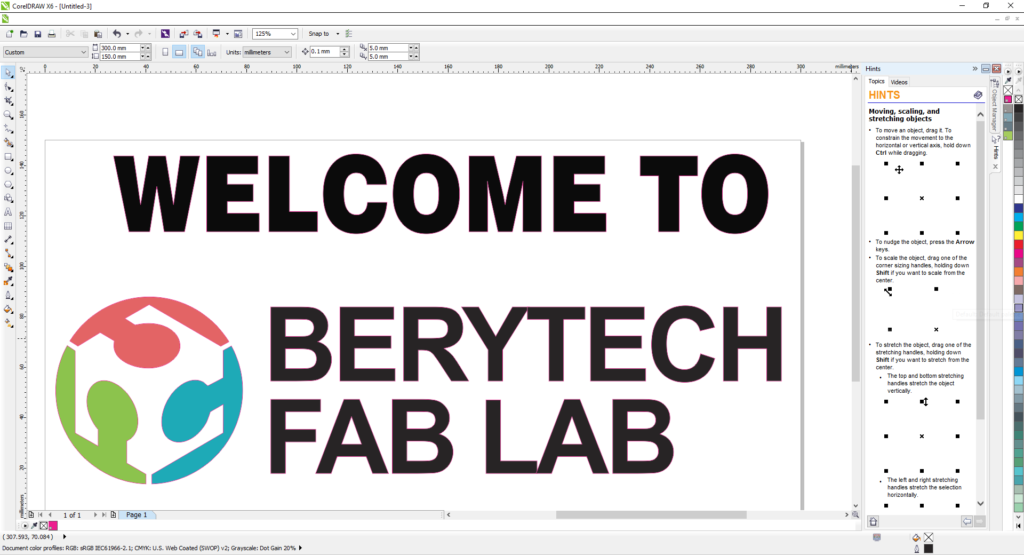
In this case we used Adobe Illustrator to design the sticker. Make sure the lines you want to cut are single continuous lines. Join lines when needed using the Join function.
Step – 15: Prepare Your Design For Printing & Cutting
Once the design is ready, the next step is to prepare your design for Printing & Cutting.
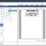
You will then import the design file into a preparation software, in our case we use CorelDraw. The sheet width should correspond to the vinyl roll width.
- Set the Correct Size & Resolution: It is important to ensure that you set your file size and resolution correctly, as failure to do this often results in an unintentional outcome. Most printers require a resolution of 300 DPI, so make sure you change this before you set a new project. The correct size is usually straight forward, as long as you know how big you want your sticker.
- Set Up Your Cut Contour: Mark your cutting outline that will be followed by the machine to cut the designed sticker. The vinyl printer recognizes the special color that can be accessed by adding Roland Bn-20 illustrator color palettes. Mark the outline that you want to cut and choose the color named “CutContour”. Make sure you set up your bleed and trim correctly. The bleed is the area outside the trim, and we do it to ensure that you are not left with an undesirable white/clear line around the edge of your sticker. Also make sure to keep your text within a safe area from the trim line, to ensure that none of the text is accidentally cut-off during the trimming process.
Save your design as.PDF or .EPS, When saving as an .EPS, Make sure to uncheck “Convert a stroke to an outline”.
Step – 16: Setting Up The Vinyl Cutter
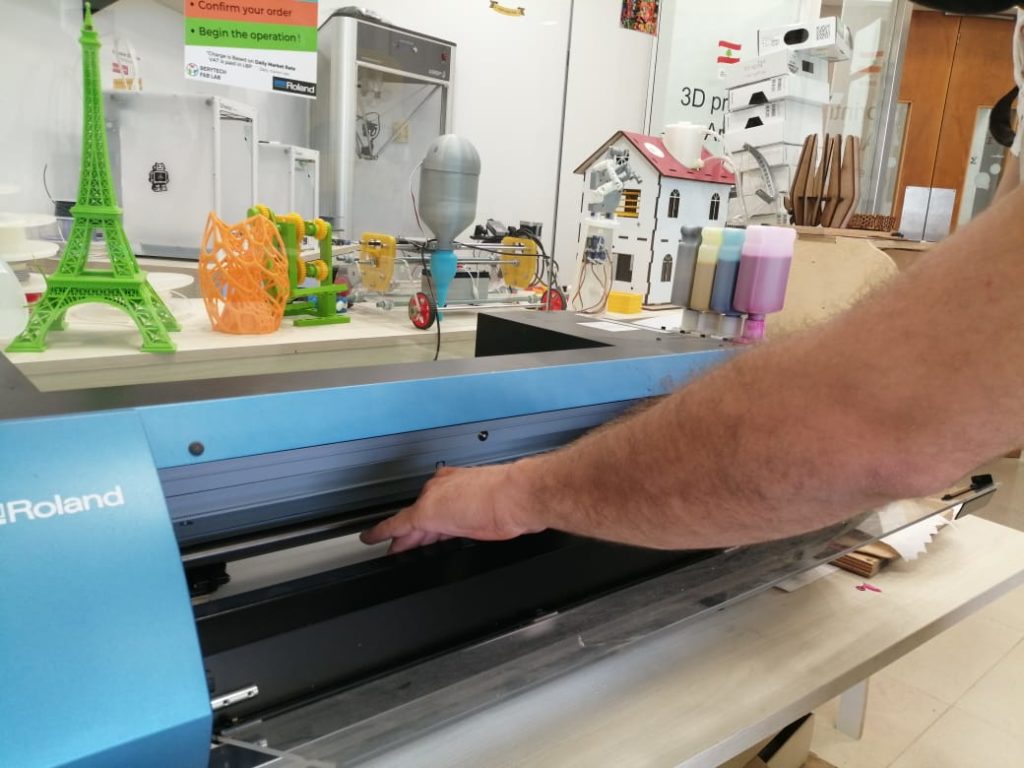
After choosing all variables, load the vinyl roll and turn on the vinyl cutter by following those steps:
- Pull the pinch roller lever and insert the material.
- Align the material with the rollers, then push the lever.
Step – 17: Input Design to Versaworks
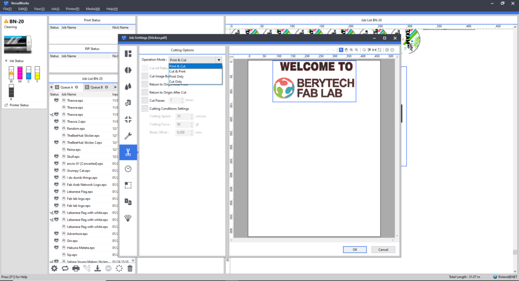
Open Roland VersaWorks and load in your file.
- Go to File>Add Job to Queue A. Your job will then appear at the bottom of Queue A.
- Double click on your loaded file to open up the Job Settings Window, In your Job Settings window, you will need to check settings in the Layout, Quality, Printer Controls and Cut Controls tabs.
- Choose the option print and cut.
- From the first option, choose “get media size” to get the width of the material we put in the machine.
- Duplicate the drawing to fill the whole width to maximize the use of vinyl cutter, and minimize material loss.
Once everything is set, forward the job from the computer. This is when the magic happens!
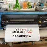
Press the print button on VersaWorks. Accordingly, the vinyl printer & cutter starts.
Step – 18: Perform The Printing & Cutting Job
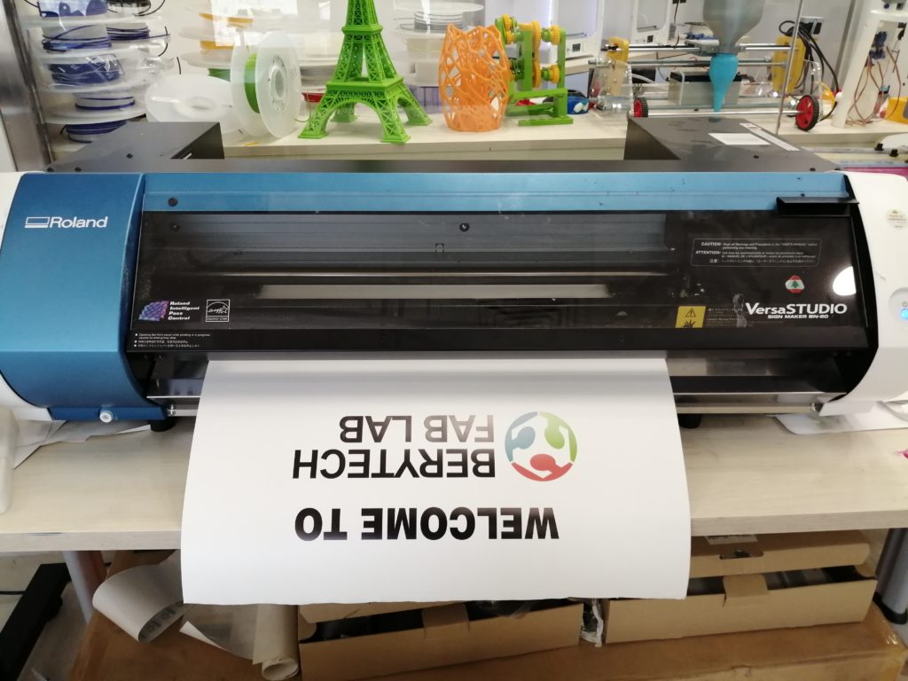
Remove your part after it is done and the vinyl is pushed forward.
Step – 19: Remove Your Media
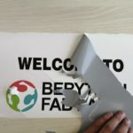
To prepare the sticker, follow those steps.
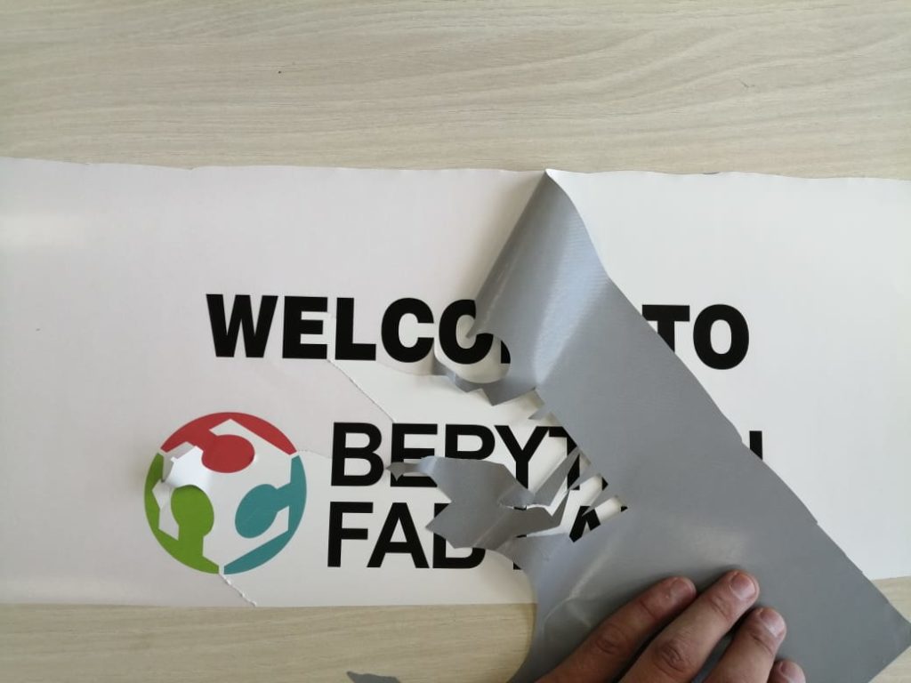
- When the print is done cut the printed part with a cutter.
- Remove all unwanted parts of the Vinyl.
- Stick a transparent adhesive film on the remaining vinyl shapes
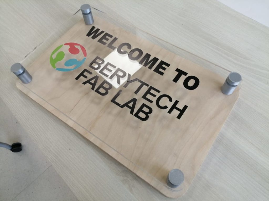
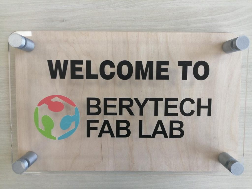
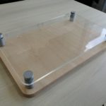
Step 20: Assembling the pieces
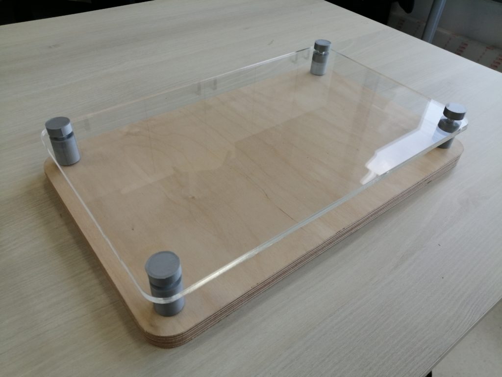
The final step is to assemble all the pieces. To do that, assemble different parts together using the nuts and bolts, and then cover bolts with the 3d printed parts.
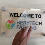
Step – 21: Transfer your sticker to the Acrylic Top
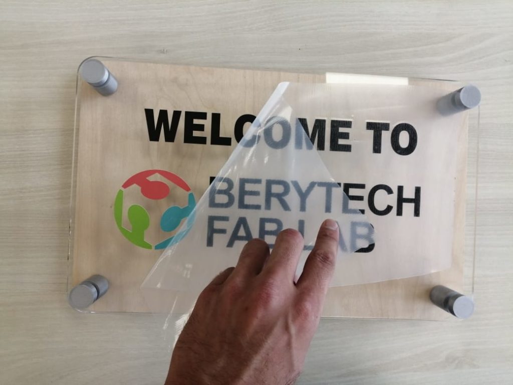
To stick your sticker onto the intended surface, follow those steps:
- Clean the surface of choice to remove any dust and impurities
- Remove the back paper support layer
- Stick the transparent sticky film with vinyl shape on the surface
- Press the vinyl onto the surface and make sure to remove all bubble stuck under it
- Slowly and carefully remove the adhesive film.