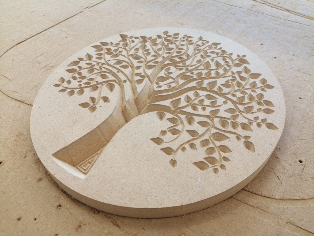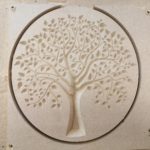
This section describes the different steps followed to produce a simple Tree of Life on wood using the V-carve option on a CNC Milling Machine at the Fab Lab.
Step 1 : Downloading the design
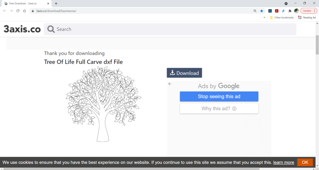
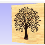
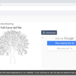
In order to digitally produce any object you need to have its digital design first. This is to be done using any Computer Aided Design (CAD) software. In this example, the design was shared for free on 3axis.co. You can download from the following Link.
Step – 2: Choose Materials and Tools you Will Use
Choose the Material you want to use to produce your milled part. Also, choose the suitable milling bit that you are planning to use to achieve your final result in a nice and efficient way.
In this example, MDF material was used for producing the 3D wood art. Multiple milling bits were used, starting with V-carving using a 60 Degree V bit, following with outline profile cutting using a 6mm diameter End Mill bit.
Those details will be used later in the V-Carve Software to prepare for the milling job.
Step – 3: Preparing G-Code on V-Carve
After that, the next step was to prepare the g-code based on our vector file
3-a: Perform the Job Setup based on Material Dimensions
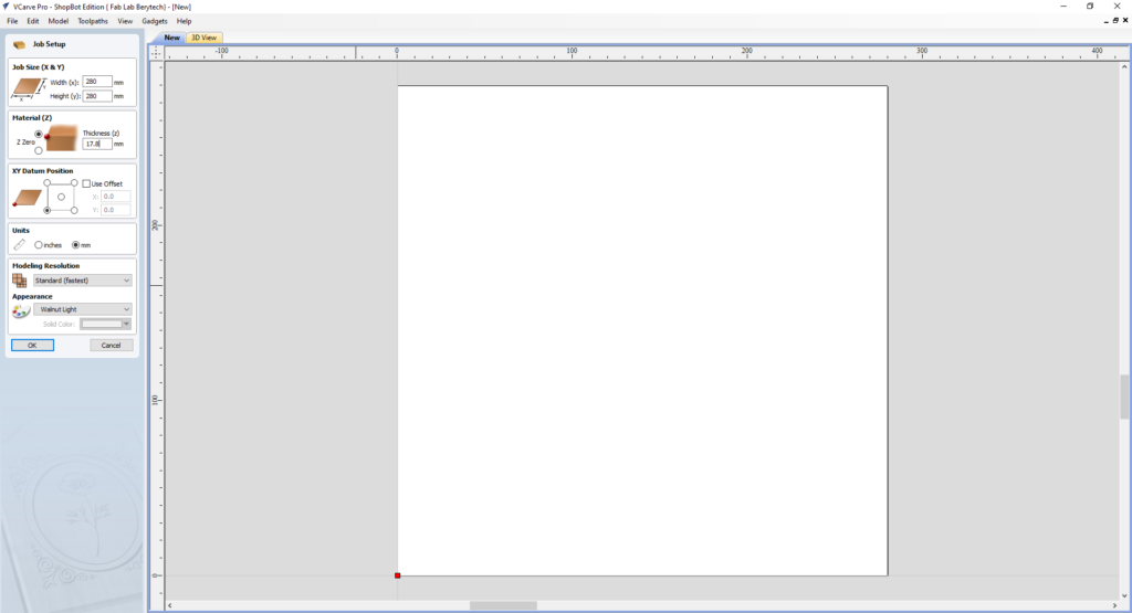
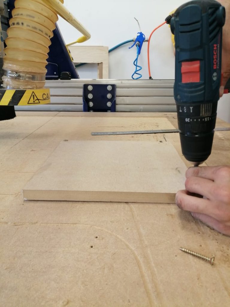
Start by setting up the dimensions of the material that you will be using. Take into consideration the lost area because of the screws used to fix the board:
- Enter the Width (x) & Height (y) for the material you are using.
- Enter the Thickness (z) for the material you are using.
- Choose the XY Datum position, which is the Zero position on the CNC machine.
When everything is set, press “OK”.
3-b: Import your 2D vector file and Choose the Best Orientation
In order to generate the toolpath for the milling job, insert the dxf file into V-Carve as follows:
- Import the DXF file by selecting: “File” > “Import” > “Import Vectors” > Choose the 2D Model
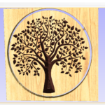
- Move your design to your preferred position of the material you are milling.
When everything is set, press “OK”.
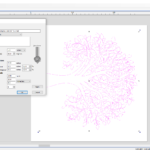
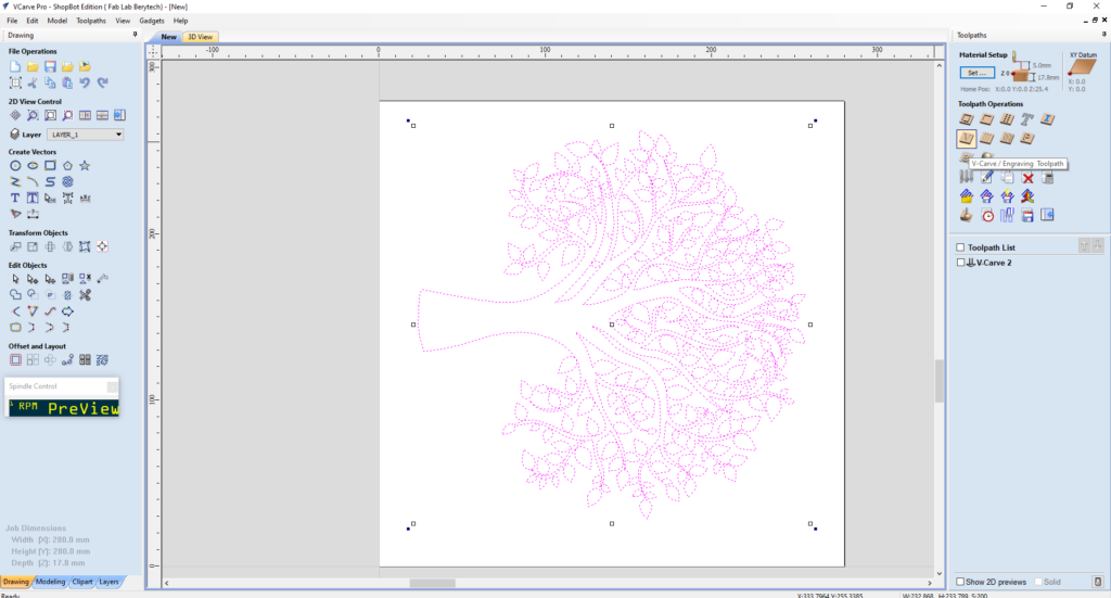
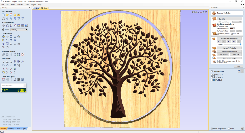
3-c: Prepare the V-Carve/Engraving Toolpath
This option is used to remove large areas of material using a V-Bit. It removes the areas contained inside the selected vectors at a certain chosen Start depth and Flat Depth. Start Depth (D) specifies the depth at which the V-Carving toolpath is calculated, allowing V-Carving / Engraving to be machined inside a pocket region. When cutting directly into the surface of a job the Start Depth will usually be 0.0.
To prepare the pocketing toolpath, follow the following steps:
- Select the “V-Carve / Engraving Toolpath” button.
- Select the tree vectors as the vectors to mill inside it.
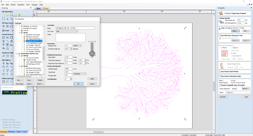
- Choose the Start Depth and Flat Depth. In this example we used 0 mm, as a start depth, and 17.5 mm as a cut depth.
- Select the tool used for outline cutting. In this example, we used a 6 Degree V-Bit.
When everything is set, press “Calculate”, to calculate your toolpath.
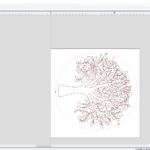
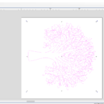
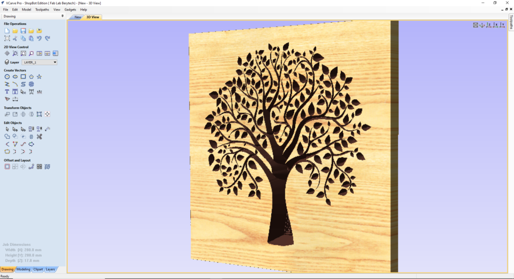
Select the “Preview Toolpath” button, to visualize the milling job, and make sure the results are as expected. If you notice any problems in the preview, make sure to go back and review all your settings to make sure that everything is running fine.
3-d: Prepare the Profile Cutting Toolpath
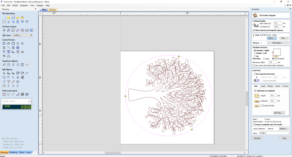
After preparing the Roughing and Smoothing toolpaths, the last step is to cut the model from the material body. To do that, prepare the 2D profile toolpath for the model:
- Select the “2D Profile Toolpath” button.
- Select the model outline as the vector followed for cutting.
- Choose the Start Depth and Cut Depth. In this example we used 18 mm, as a cut depth, as the board we are using is 18 mm thick.
- Select the tool used for outline cutting. In this example, we used a 6mm Diameter End Mill.
- Choose your preferred machining tool position with respect to the chosen outline vector. In this example we choose the “Outside” option, so that the tool cut the material outside the outline vector.
- Add tabs to the toolpath to keep the part in position and connected to the main body, to prevent it from moving and getting loose. Those tabs will be removed manually after milling to remove the part.
When everything is set, press “Calculate”, to calculate your toolpath.
Select the “Preview Toolpath” button, to visualize the milling job, and make sure the results are as expected. If you notice any problems in the preview, make sure to go back and review all your settings to make sure that everything is running fine.
3-h: Save the Toolpaths
After doing the v-carving and profile cutting toolpaths, save the toolpath files in your dedicated folder.
To do that, select the “Save Toolpath” button. This option allows toolpaths to be saved in the appropriate file format needed to drive the CNC machine.
Step – 4: Preparing the CNC Machine and Zeroing the Tool Position
Next we need to set the zero position for the machine on the board we are using.
To do so, we need to open the Shopbot Software, select the Control Panel and follow those steps.
- Manually move the router to the desired X and Y position, and then zero the X and Y from the control panel
- Zero the Z-Axis using the automatic zeroing option on the Shopbot. The plate is positioned under the router on the surface of the board, and the Z-zero button is pressed. The process is fully automatic.
Step – 5: Performing the Milling Job
Next we perform the milling job. Just import the G-code to the Shopbot software and launch the jobs one by one. The video illustrates the milling job. Make sure to change the milling tools in between the jobs, based on the prepared toolpaths.
Step – 6: Remove the Part
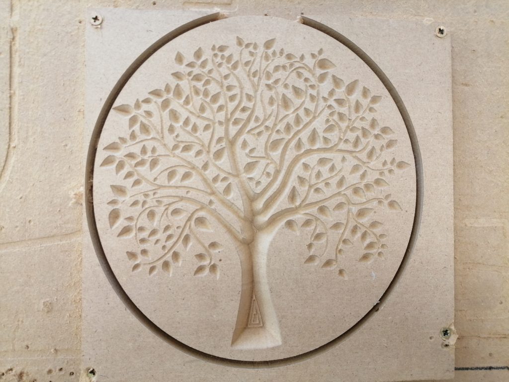
The final step is to cut the tabs using a wood chisel and remove the part from the main body . Enjoy your new 3d wood art.
Note: This document was written with the help of the V-Carve Manual found on the following Link