This section describes the different steps followed to produce any 3D shape, from any wooden piece, using 3D CNC Milling at the Fab Lab.
Step – 1 : Download the 3D Model
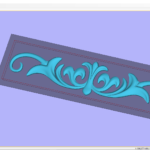
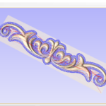
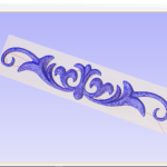
In order to produce a 3D object you first need to have its digital design. This can be designed using any Computer Aided Design (CAD) software.
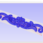
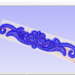
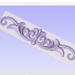
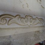
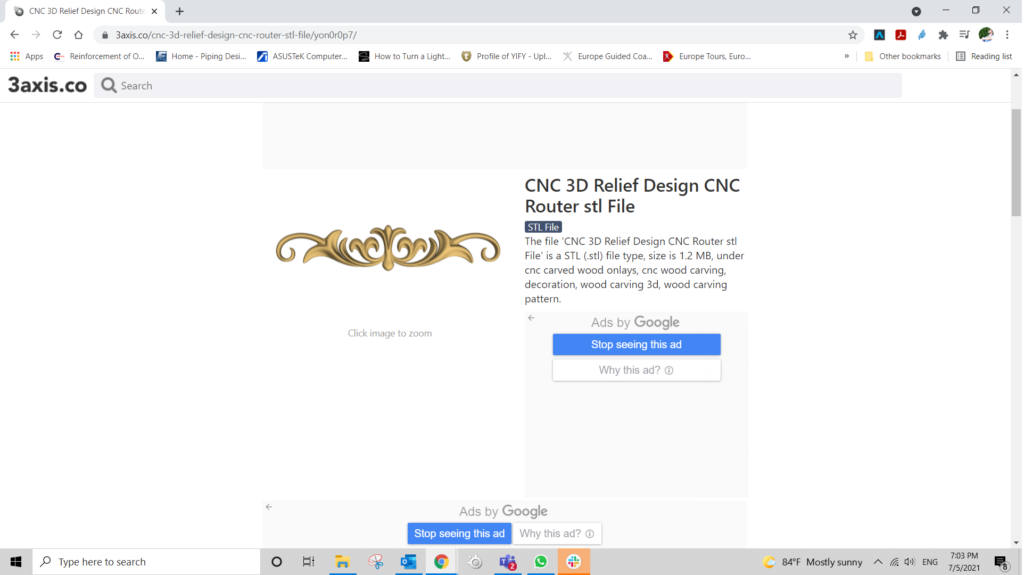
In this example, the design was downloaded for free from 3axis.co. (Link attached above).
Step – 2: Choose Materials and Tools you Will Use
Choose the Material you want to use to produce your milled part. Also, choose the suitable milling bits that you are planning to use to achieve your final result in a nice and efficient way.
3D Milling is usually done in multiple steps, starting with Roughing using bigger tools, then moving to smoothing using smaller bits. Smoothing can be performed in multiple stages using many bits to reduce the stress on the smaller bits used.
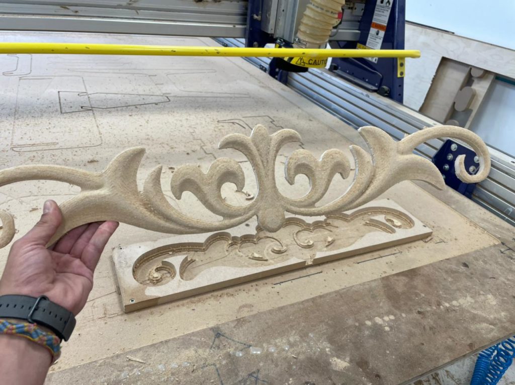
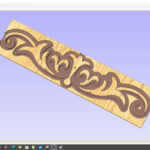
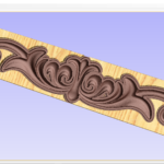
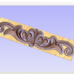
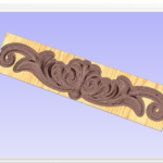
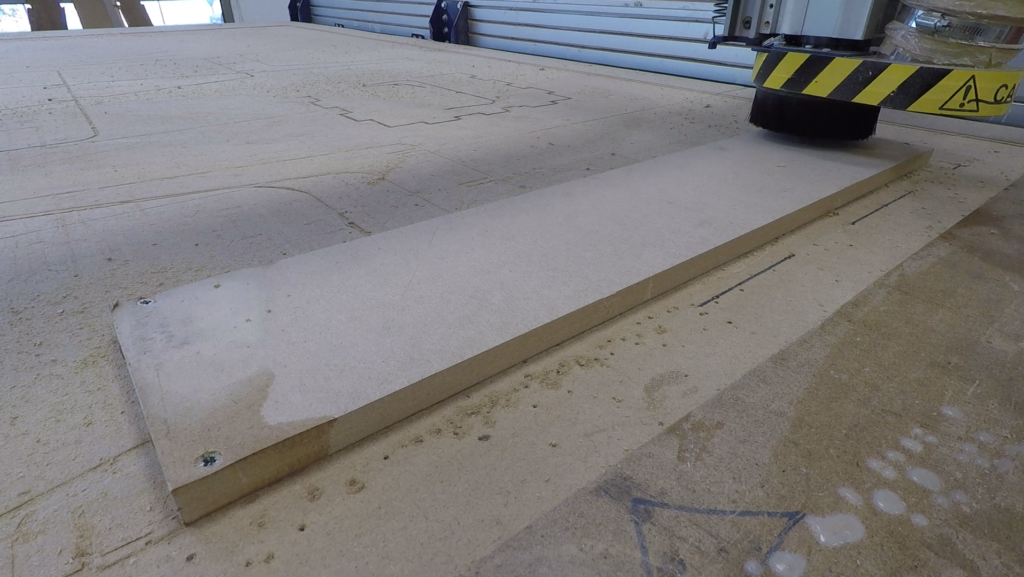
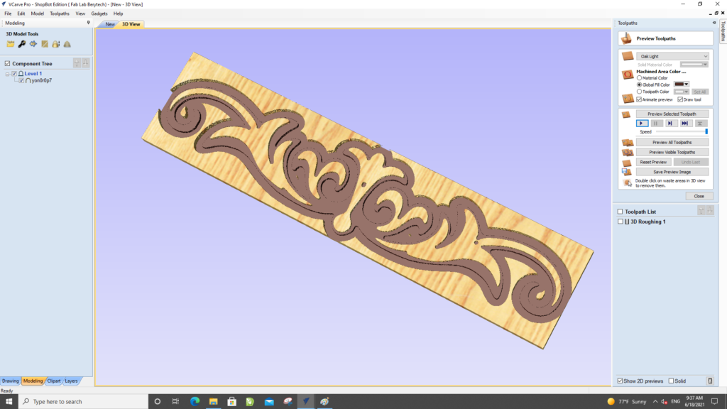
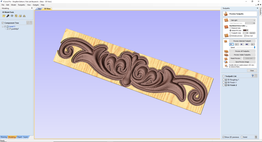
In this example, MDF was used for producing the 3D wood art. Multiple milling bits were used, starting with Roughing using a 6mm End Mill Bit, following with Smoothing using a 6mm Ball Nose Bit, and Finally a 3mm Ball Nose bit to get the best final finish.
Those details will be used later in the V-Carve Software to prepare for the milling job.
Step – 3: Preparing G-Code on V-Carve
After that, the next step was to prepare the g-code based on our 3d model.
3-a: Perform the Job Setup based on Material Dimensions
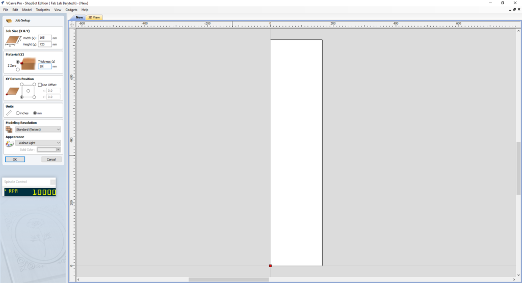
Start by setting up the dimensions of the material that you will be using. Take into consideration the lost area because of the screws used to fix the board:
- Enter the Width (x) & Height (y) for the material you are using.
- Enter the Thickness (z) for the material you are using.
- Choose the XY Datum position, which is the Zero position on the CNC machine.
When everything is set, press “OK”.
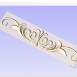
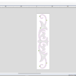
3-b: Import your 3D model and Choose the Best Orientation
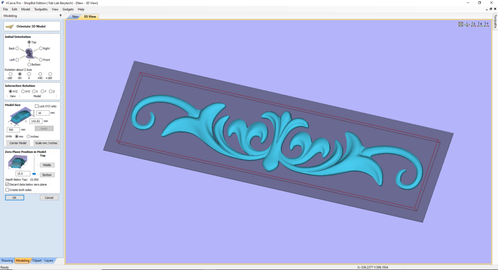
In order to generate the toolpath for the milling job, insert the model into V-Carve as follows:
- Import the STL file by selecting: “File” > “Import” > “Import Component / 3D Model” > Choose the 3D Model
- Choose the best Initial Orientation for your object by selecting the best initial orientation that you want to mill.
- Edit your model size based on your specifications and limitations (Materials and Tools Available). In this example, the model was scaled on the z-axis to fit on an 20mm board.
- Choose the best position for your object. You can use the “Center Model” button for easy centering in the board.
- Set the location of the Zero Plane Position with respect to your model. This will allow you to choose which parts of the 3d model you want to engrave, and disregard anything under it. In this case, we wanted to engrave the whole model.
When everything is set, press “OK”.
3-c: Perform the Material Setup
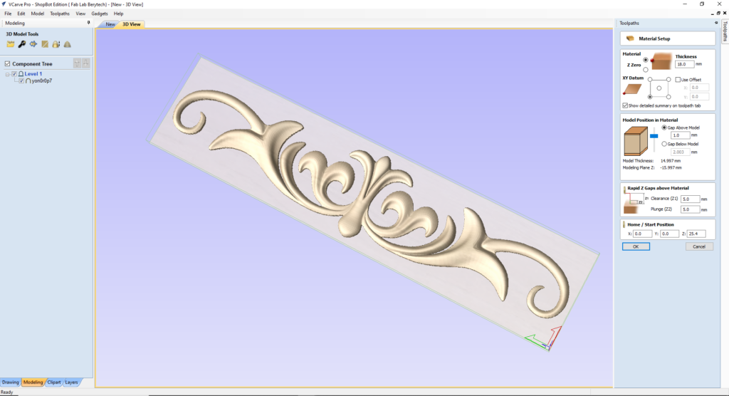
The Material Setup section of the Toolpaths tab provides a summary of the current material settings. Some of these values will have been initially set when the job was first created .
When you come to creating toolpaths, it is important to review this information and ensure it is still valid and also to set the machining clearances.
In order to setup the material for the milling job, click on the “Set…” button to open the Material Setup form:
- Review the Thickness of the Material Used
- Make sure the XY Datum position is correct, which is the Zero position on the CNC machine.
- Choose the Z-Zero position of your choice
- Choose the best position for your object in the Material. You can choose the Gap Above Model and the Gap Below Model.
- Set the best Rapid Z Gaps above the material
- Make sure the Home / Start Position are correct.
When everything is set, press “OK”.
3-d: Prepare the Roughing Toolpath
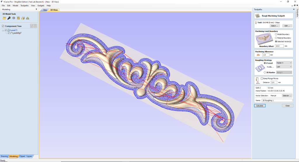
After setting the position of the model, prepare first the roughing toolpath for the model:
- Select the “3D Roughing Toolpath” button
- Select the tool used for roughing. In this example, we used a 6mm Diameter End Mill.
- Choose the Machining Limit Boundary, which is the area that should be milled. In this example we choose the Model Boundary with an offset of 10mm.
- Choose your preferred machining allowance based on the design and your preferences. In this example we choose 1mm.
- Choose the Roughing Strategy that you prefer. You can choose roughing by milling layer by layer by selecting the “Z level” option, or 3D Roughing by choosing “3D Raster”. In this example, we used the Z level option.
When everything is set, press “Calculate”, to calculate your toolpath.
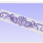
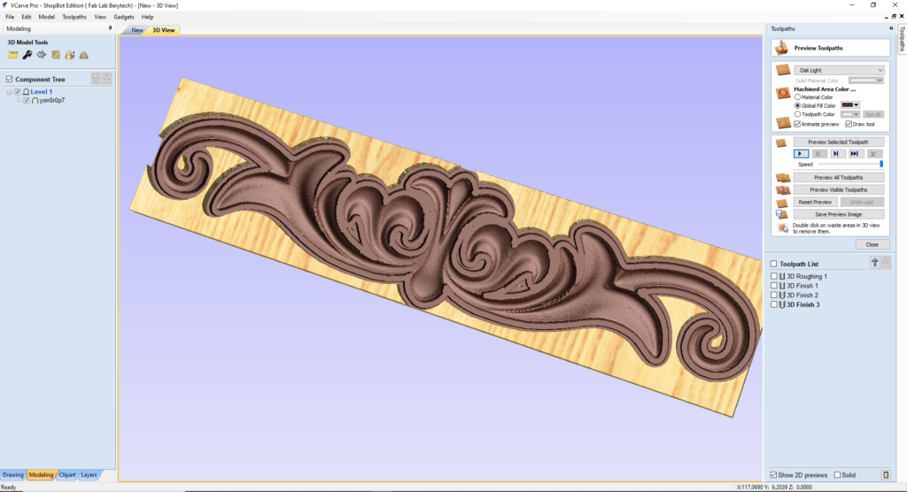
Select the “Preview Toolpath” button, to visualize the milling job, and make sure the results are as expected. The 3D preview mode also allows the job to be viewed in different material types with the option to paint the machined regions with a Fill Color. If you notice any problems in the preview, make sure to go back and review all your settings to make sure that everything is running fine.
3-e: Prepare the Smoothing Toolpath
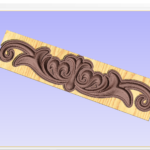
After doing the roughing toolpath, the next step is to prepare the smoothing toolpath for the model. In this example we did smoothing in multiple steps using various tools, to achieve a better quality and reduce stress on small tools. We started by using a 6mm Ball Nose Mill, then a 3mm Ball Nose to achieve the best Final Quality .
3-e-1: 6mm End Mill
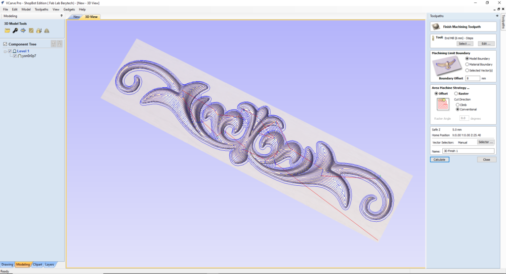
- Select the “3D Finishing Toolpath” button
- Select the tool used for smoothing. In this example, we used a 6mm Diameter End Mill.
- Choose the Machining Limit Boundary, which is the area that should be milled. In this example we choose the Model Boundary with a 6mm Offset.
- Choose the Area Machine Strategy that you prefer. You can choose smoothing starting from the center towards the edge using the “offset” option, or smoothing line by line, by choosing “Raster” option. In this example, we used the offset option.
- Calculate your toolpath
- Preview the toolpath to check if the results are acceptable, and make sure your settings are correct.

3-e-2: 6mm Ball Nose Mill
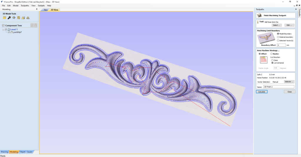
Select the “3D Finishing Toolpath” button
Select the tool used for roughing. In this example, we used a 6mm Diameter Ball Nose Mill.
Choose the Machining Limit Boundary, which is the area that should be milled. In this example we choose the Model Boundary with a 6mm Offset.
Choose the Area Machine Strategy that you prefer. You can choose smoothing starting from the center towards the edge using the “offset” option, or smoothing line by line, by choosing “Raster” option. In this example, we used the offset option.
Calculate your toolpath
Preview the toolpath to check if the results are acceptable, and make sure your setting are correct.
3-e-3: 3mm Ball Nose Mill
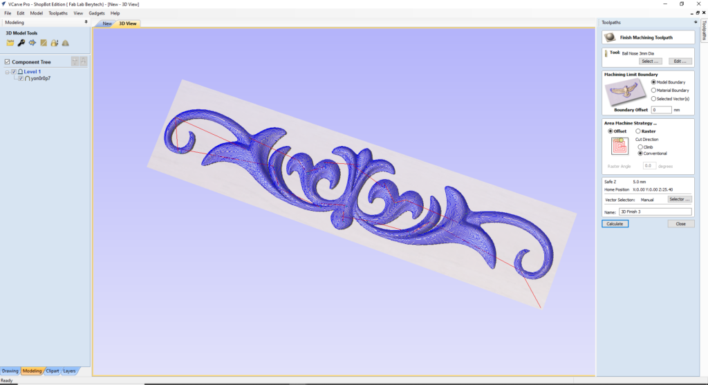
- Select the “3D Finishing Toolpath” button
- Select the tool used for roughing. In this example, we used a 3mm Ball Nose Mill.
- Choose the Machining Limit Boundary, which is the area that should be milled. In this example we choose the Model Boundary with a 6mm Offset.
- Choose the Area Machine Strategy that you prefer. You can choose smoothing starting from the center towards the edge using the “offset” option, or smoothing line by line, by choosing “Raster” option. In this example, we used the offset option.
- Calculate your toolpath
Preview the toolpath to check if the results are acceptable, and make sure your setting are correct.
3-f: Prepare the Profile Cutting Toolpath
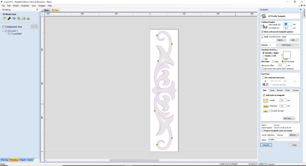
After preparing the Roughing and Smoothing toolpaths, the last step is to cut the model from the material body. To do that, prepare the 2D profile toolpath for the model:
- Select the “2D Profile Toolpath” button.
- Select the model outline as the vector followed for cutting.
- Choose the Start Depth and Cut Depth. In this example we used 24.1mm, as a cut depth, as the board we are using is 24mm thick.
- Select the tool used for outline cutting. In this example, we used a 6mm Diameter End Mill.
- Choose your preferred machining tool position with respect to the chosen outline vector. In this example we choose the “Outside” option, so that the tool cut the material outside the outline vector.
- Add tabs to the toolpath to keep the part in position and connected to the main body, to prevent it from moving and getting loose. Those tabs will be removed manually after milling to remove the part.
When everything is set, press “Calculate”, to calculate your toolpath.
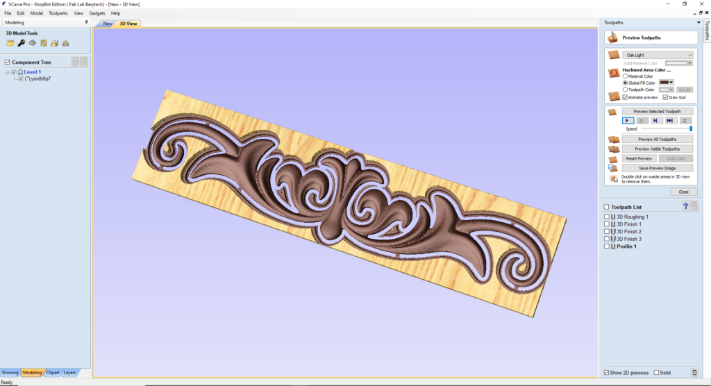
Select the “Preview Toolpath” button, to visualize the milling job, and make sure the results are as expected. If you notice any problems in the preview, make sure to go back and review all your settings to make sure that everything is running fine.
3-g: Check the Total Machining Time
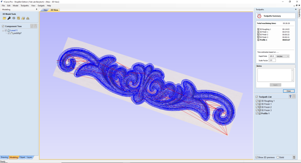
Check how long each machining toolpath will take, to estimate how much time it requires for production.
To do that, select the “Toolpaths Summary” button In this example, the whole milling process takes around 37 mins. Please note that the real production time includes the time that you take to fix the material, set the zero position for the machine, changing the milling bit between jobs, and removing the part once it is done.
3-h: Save the Roughing and Smoothing Toolpath
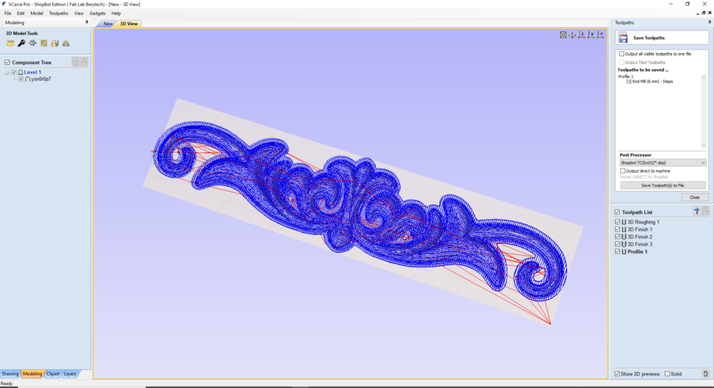
After doing the roughing, smoothing and cutting toolpaths, save the toolpath files in your dedicated folder.
To do that, select the “Save Toolpath” button. This option allows toolpaths to be saved in the appropriate file format needed to drive the CNC machine.
Step – 4: Preparing the CNC Machine and Zeroing the Tool Position
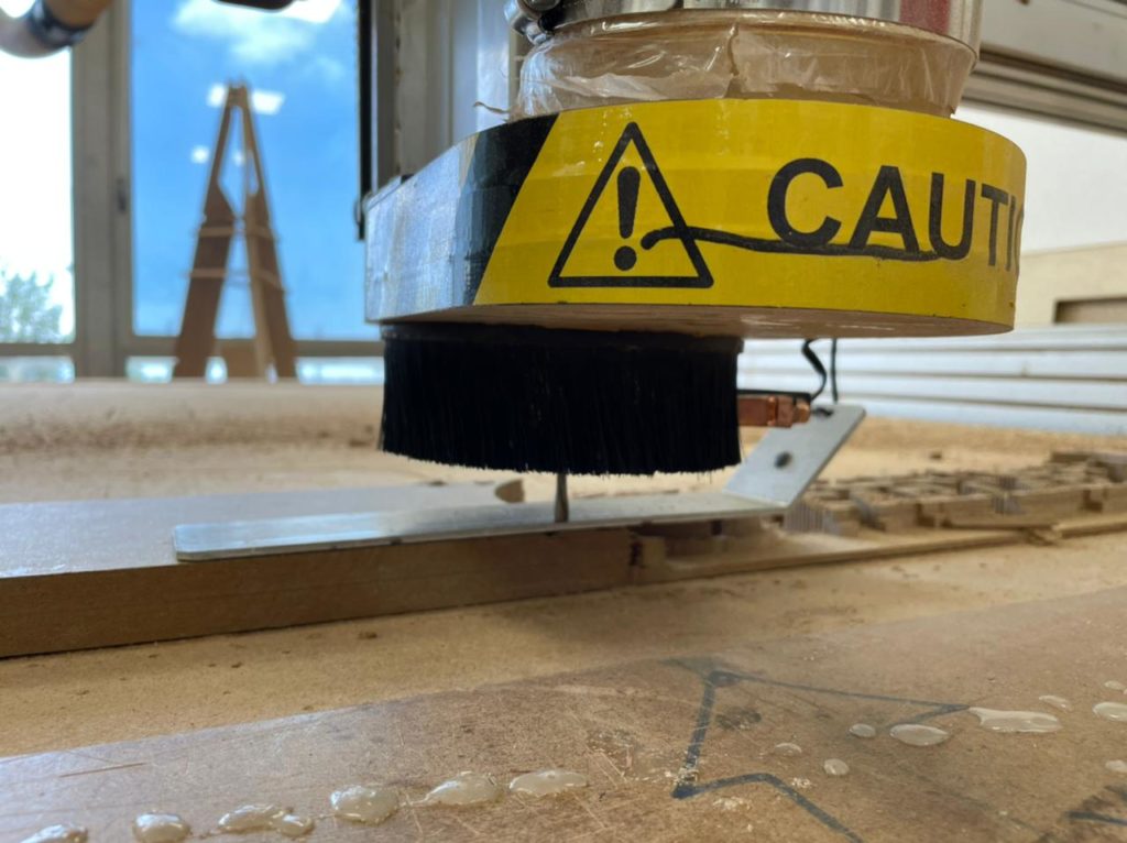
Next we need to set the zero position for the machine on the board we are using.
To do so, we need to open the Shopbot Software, select the Control Panel and follow those steps.
- Manually move the router to the desired X and Y position, and then zero the X and Y from the control panel
- Zero the Z-Axis using the automatic zeroing option on the Shopbot. The plate is positioned under the router on the surface of the board, and the Z-zero button is pressed. The process is fully automatic.
Step – 5: Performing the Milling Job
Next we perform the milling job. Just import the G-code to the Shopbot software and launch the jobs one by one. The video illustrates the milling job. Make sure to change the milling tools in between the jobs, based on the prepared toolpaths.
Step – 6: Remove the Part
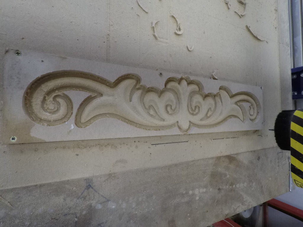
The final step is to cut the tabs using a wood chisel and remove the part from the main body . Enjoy your new 3d piece.
Note: This document was written with the help of the V-Carve Manual found on the following Link