This section describes the different steps followed to produce Forest Shelves of your own at the Fab Lab.
Step 1 : Downloading the design
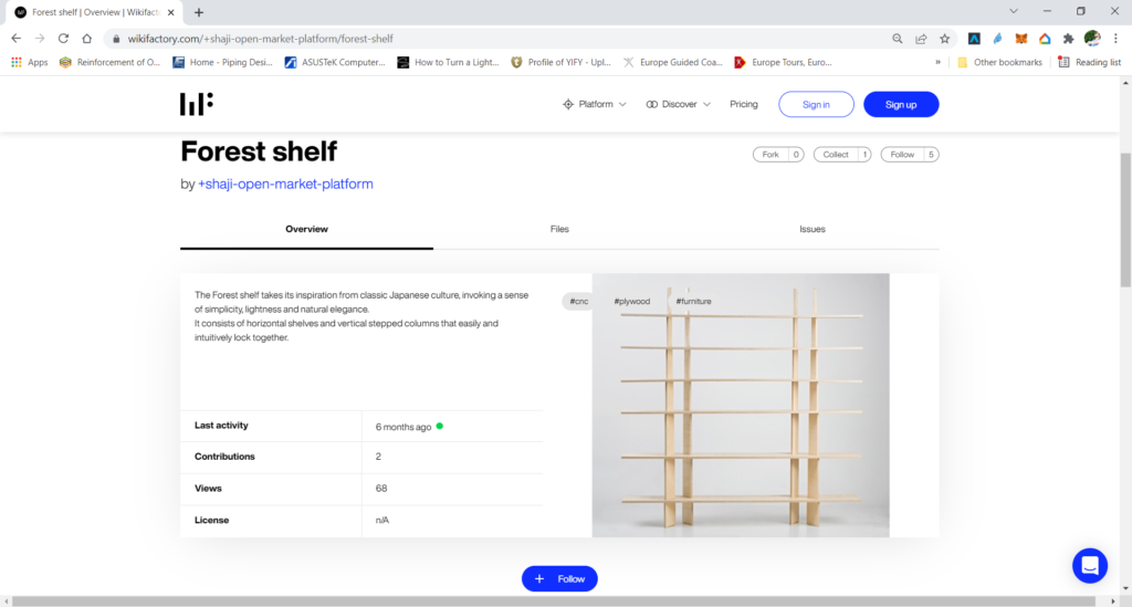
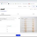
In order to produce any furniture item you need to have its digital design first. This is to be done using any Computer Aided Design (CAD) software. Those shelves were designed by Shaji Open Market Project and are available to download on wikifactory . The design can be accessed on the following Link.
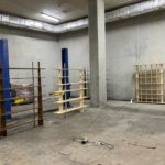
It is important to note that the shelve designs are very flexible, and they are available in various lengths, to fit anywhere. At the lab we tried many lengths that can be seen at the end of step 6.
Step 2: Choose Material, Test it and Edit Design
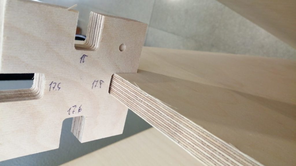
The next step is to choose the material that you would like to use. In this example, we used 18mm Birch Plywood Sheets. However, It is worth making some test pieces to check the fit before producing on a large scale, to prevent any errors.
We do this step because Wood Boards are not 100% 18mm, and the dimensions usually vary, so to achieve a perfect fit, we measure the real dimensions using a caliper, and edit our design accordingly.
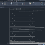
Accordingly, extract the Sketch in DXF file and edit the slot width to match the measure dimensions and your test results. In this example, the slots were edited to become 17.8 mm as per the real board thickness.
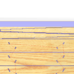
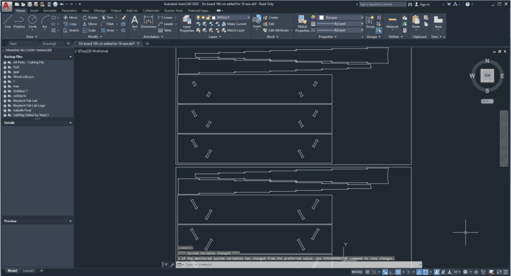
The DXF file was then edited to add T-bones at 90 degrees corners in the joints. This step is done because a round bit cannot mill 90 degrees. This will guarantee that all parts fit together.
Finally, a file was prepared that contains all the pieces needed to form the table , fitting them all inside a rectangle that has the same dimensions of the board we are using. This file will then be Imported to the V-Carve Software for G-code preparation.
Step 3: Preparing G-Code on V-Carve
After that, the next step was to prepare the g-code based on our design.
The steps to set up V-Carve are as follows:
- Open new page.
- Job Setup: Input Board Dimensions (x, y, & z). Take into consideration the lost area because of the screws used to fix the board.
- Import the DXF file by selecting: “File” > “Import” > “Import Vectors” > Choose the 2D Model
- Move your design to your preferred position of the material you are milling.
- Generate the Path for the inner cuts and then the exterior cuts. To do so the following steps are followed:
- Select the “2D Profile Toolpath” button.
- Select the vector you want to follow for cutting.
- Choose the Start Depth and Cut Depth. In this example we used 18.1mm, as a cut depth, as the board we are using is 18mm thick.
- Select the tool used for outline cutting. In this example, we used a 6mm Diameter End Mill.
- Add tabs to the toolpath to keep the part in position and connected to the main body, to prevent it from moving and getting loose. You can either set them automatically or just press on the cutting path to add a tab in your preferred positions. Those tabs will be removed manually after milling to remove the part.
- Add Ramps if needed, to reduce the load on the tool.
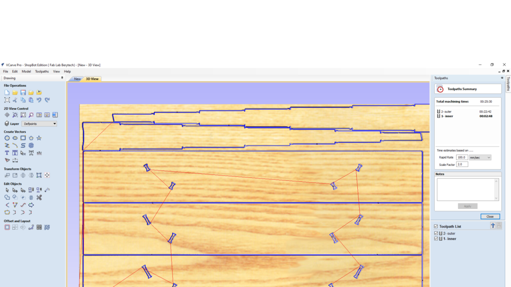
- When everything is set, press “Calculate”, to calculate your toolpath. Select the “Preview Toolpath” button, to visualize the milling job, and make sure the results are as expected. If you notice any problems in the preview, make sure to go back and review all your settings to make sure that everything is running fine.
- Check Machining time to estimate the overall production time and plan accordingly.
- Save Toolpath files in your dedicated folder.
Step 4: Preparing the CNC Machine and Zeroing the Tool Position
Next we need to set the zero position for the machine on the board we are using.
To do so, we need to follow those steps.
- Manually move the router to the desired X and Y position, and then zero the X and Y from the control panel
- Zero the Z-Axis using the automatic zeroing option on the Shopbot. The plate is positioned under the router on the surface of the board, and the Z-zero button is pressed. The process is fully automated.
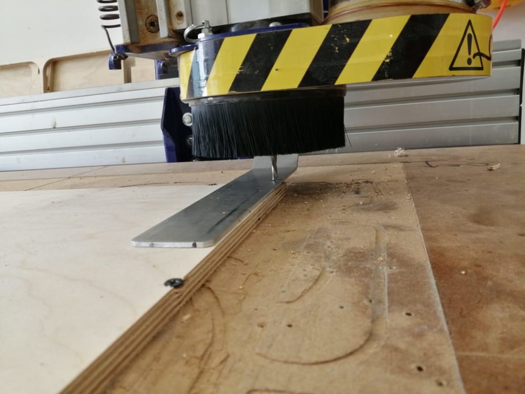
Step 5: Performing the Milling Job
Next we perform the milling job. Just import the G-code to the Shopbot software and launch the job. The video above illustrates the the milling job and the final products. The final step is to cut the tabs using a wood chisel and remove the part from the main body.
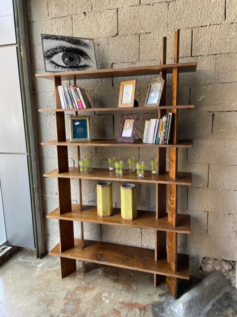
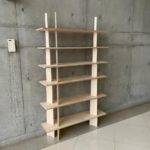
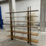
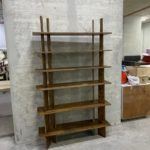
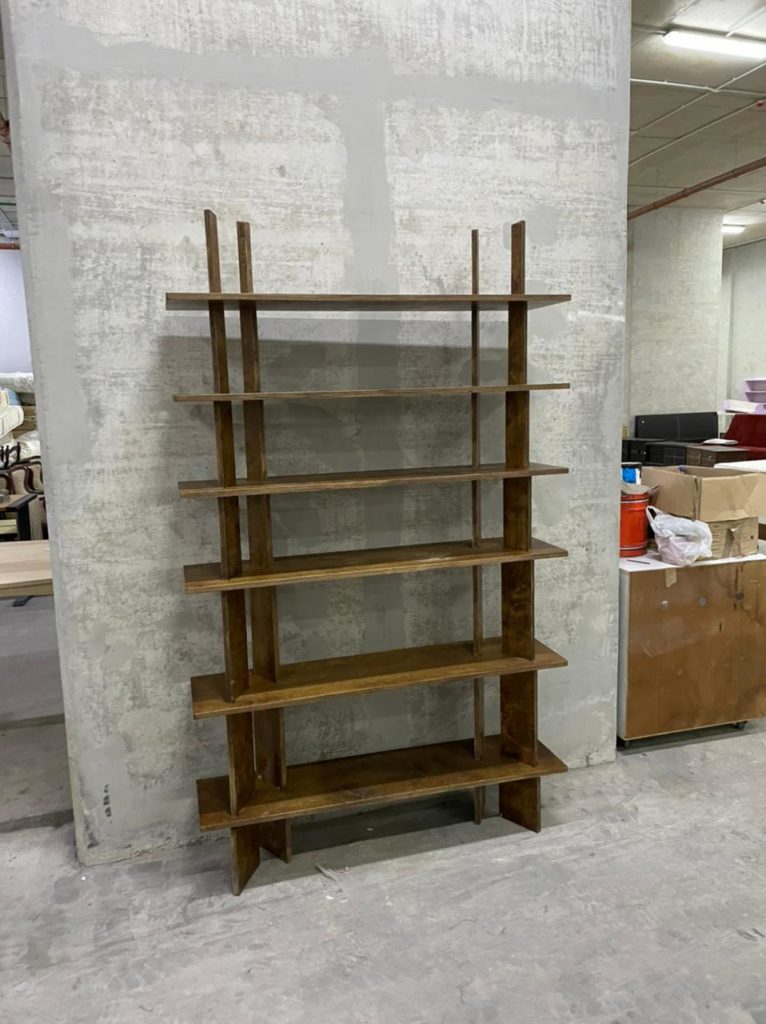
Step 6: Assembling the pieces
The final step is to assemble all the pieces. Enjoy your new Forest Shelves.
At the lab we produces shelves of various lengths. Shelves were also painted in different colors to have different finishing results.
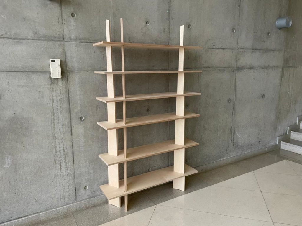
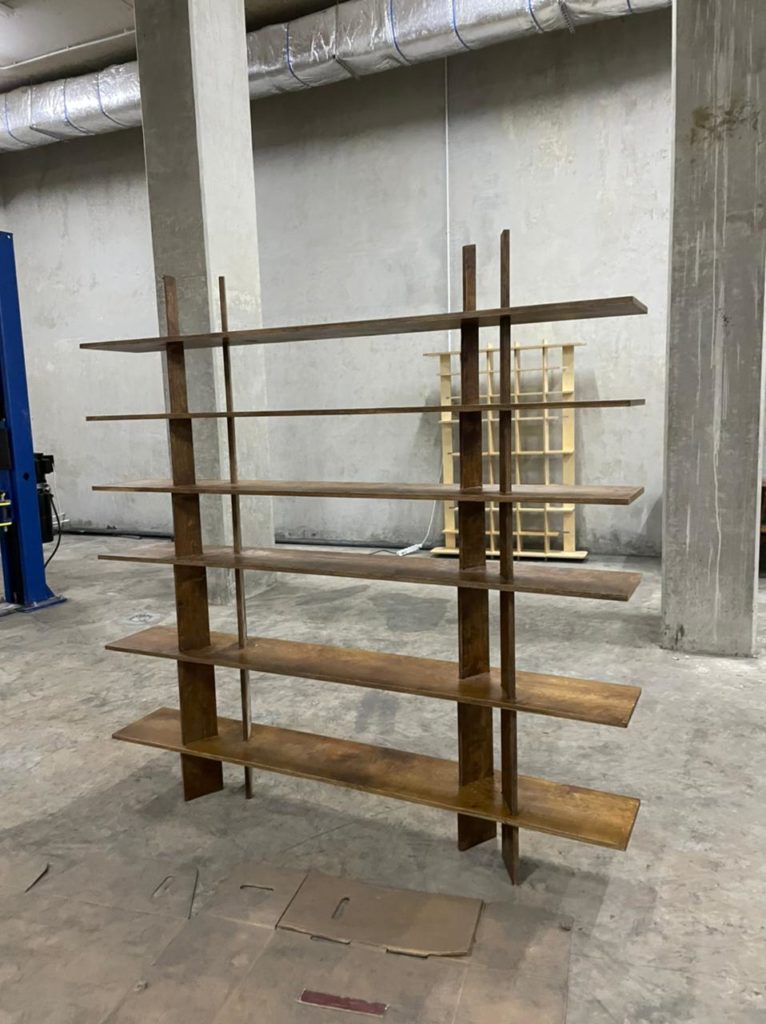
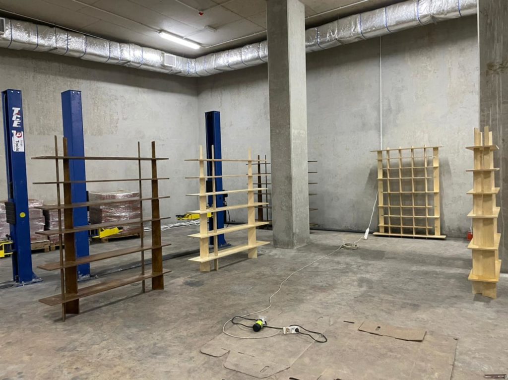
Hope you like them.